
Carrier Grade Addendum - rp5400 Series of Servers


Chapter 1
Installation
Connecting the Server to DC Power Source
21
Cable Strain Relief
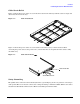
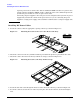
Figure 1-4 shows the power cables are secured to the bottom of the side tray with the cable tie wraps and
attached to the front of the tray.
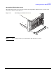
Figure 1-4 Cable Installation
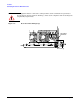
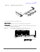
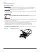
Figure 1-5 shows the power cables are secured at the back of the tray by a strain relief bar. When
connecting the power cables to the power source, ensure that there is enough slack in the cables to fully
extend the tray.
Figure 1-5 Cable Strain Relief
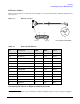
Safety Grounding
The rp5400 Series of Server Carrier Grade System has a grounding lug on the rear panel for connecting to
earth ground. The server must be connected to earth ground using a minimum 6 AWG (16mm
2
) wire with a
suitable Listed/Certified terminal such as Thomas and Betts part number 54205.
Strain Relief Bar
Strain Relief Sleeve