
Carrier Grade Addendum - rp5400 Series of Servers


Chapter 1
Installation
Installing the Server in a Rack
12
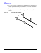
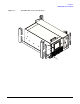
Install the Slider Assembly
The following steps describe how to install the slide-tray assembly into an approved HP equipment
enclosure. The slide-tray assembly can be installed into an HP E-Series enclosure and some other approved
HP enclosures.
NOTE If compliance with Belcore GR63 CORE earthquake standards is required, the enclosure
used should be NEBS compliant.
Perform this procedure to preparation for field integration of a slide-tray mountable server in an approved
enclosure. To prepare an equipment enclosure for field integration of a server proceed as follows:
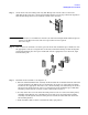
Step 1. Determine whether or not the enclosure into which you will install the slide/tray kit is a E-Series
or an approved non-E-Series enclosure.
The non-E-Series enclosure has full return flanges on the vertical mounting rails where the
E-Series enclosure has only partial return flanges on the vertical mounting rails.
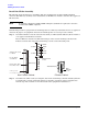
Step 2. Determine into which vertical, rectangular, slots in the return flanges that the slide/tray kit will
be installed. To correctly position the slide tray assembly, count down eight rectangular slots
from the top of the enclosure or from the bottom of the equipment installed above.
1
5
.
8
7
5
1
5
.
8
7
5
1
2
.
7
1
5
.
8
7
5
1
5
.
8
7
5
1
2
.
7
M
e
a
sur
e
m
e
nt
s
in mm.
U
=
4
4
.
4
5
U
=
4
4
.45
2
U
E
nv
e
lo
p
e
Support Notches
for Rails
Front (Rear)
of Cabinet
Every Fifth Rail
Hole Notched
E
I
A S p a ced
Moun
t
i
ng H o
l
es
One
EIA unit
or “U”
Threaded inserts
E-Series CabinetNon E-series Cabinet