
Managing HP Serviceguard A.12.00.00 for Linux, June 2014
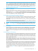
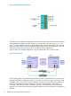
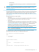
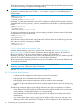
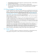
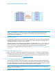

Figure 22 Bonded Network Interfaces
The LANs in the non-bonded configuration have four LAN cards, each associated with a separate
non-aggregated IP address and MAC address, and each with its own LAN name (eth1, eth2,
eth3, or eth4). When these ports are aggregated, all four ports are associated with a single IP
address and MAC address. In this example, the aggregated ports are collectively known as bond0,
and this is the name by which the bond is known during cluster configuration.
Figure 3-18 shows a bonded configuration using redundant hubs with a crossover cable.
Figure 23 Bonded NICs
Node1
Node2
bond0:
eth0
eth1
bond0:
eth0
eth1
active
active
Crossover cable
Hub
Hub
In the bonding model, individual Ethernet interfaces are slaves, and the bond is the master. In the
basic high availability configuration (mode 1), one slave in a bond assumes an active role, while
the others remain inactive until a failure is detected. (In Figure 3-18, both eth0 slave interfaces are
active.) It is important that during configuration, the active slave interfaces on all nodes are
connected to the same hub. If this were not the case, then normal operation of the LAN would
require the use of the crossover between the hubs and the crossover would become a single point
of failure.
62 Understanding Serviceguard Software Components