
HP RIP Software - User Guide

Creating a Color Profile 4-15
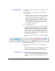
Print Ramp Limits 11. Select the Primary Device, which will be used to read the color pro-
filing target.
12. Click the radio button marked ‘Print and read external device’s
ramp patches or:
• (Optional) To read color or linearization data from a file created
by a previous profile creation process, check the appropriate
checkbox and select the file from the drop-down lists.
• (Optional) To allow future calibrations (linearizations) using the
printer’s onboard digital imaging sensor (camera), check the
box labeled, “Allow camera calibration.” You can also read a
camera data file from a previous calibration by checking the
box, “Read camera’s data from file.”
13. Click the Next ( ) button.
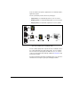
This initializes the linearization process to determine ink maxima.
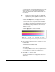
The printer prints the linearization targets so you can read them
with the external device. Depending on the color set and width of
the media, the patches may need to be printed in two sets. The
patches are shown as they are read, and the first patch of each
printed row will be outlined in green with a row number. When you
hover the mouse cursor over a patch, the row and patch numbers
and reading value are displayed.
If you need to re-read a row, click the row, then click the Replace
button.
14. After all of the patches have been read, click the Submit ()
button.
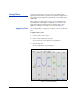
The Set Ink Limits tab appears. This tab displays the newly-created
hue angle curve (generated from the linearization data), and
enables you to set the ink channel limits for each ink channel.
Set Ink Limits 15. Set the ink channel limits for each color, either by entering a
numeric value, or by selecting (with the radio buttons) hue angle
curve for one of the ink colors and clicking where the curve begins
to flatten out or change its slope. Only the CMYK curves can be
changed.
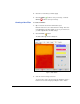
Fig. 4-6. Linearization targets