HP XP External Storage Software User Guide HP XP12000 Disk Array HP XP10000 Disk Array HP 200 Storage Virtualization System nl nl Abstract This document provides information about preparing for, performing, and troubleshooting HP XP External Storage operations; connecting external arrays; and using an XP12000/XP10000/SVS200 with EVA3000/50000.
© Copyright 2007, 2011 Hewlett-Packard Development Company, L.P. Confidential computer software. Valid license from HP required for possession, use or copying. Consistent with FAR 12.211 and 12.212, Commercial Computer Software, Computer Software Documentation, and Technical Data for Commercial Items are licensed to the U.S. Government under vendor's standard commercial license. The information contained herein is subject to change without notice.
Contents 1 Overview of connecting external arrays.........................................................7 XP External Storage features.......................................................................................................7 2 Preparing for XP External Storage operations.................................................9 Supported storage platforms and firmware...................................................................................9 Prerequisites...................................
Device tree........................................................................................................................58 Device list.........................................................................................................................59 WWN tree.......................................................................................................................62 WWN list.........................................................................................................
6 Troubleshooting NAS Blade systems that include external arrays...................119 Stopping and restarting external arrays...................................................................................119 Stopping external arrays...................................................................................................120 Restarting external arrays and restoring NAS Blade systems...................................................120 Recovery procedures for errors in external arrays..........
Path status and examples of recovery procedures (SVS200)...................................................155 Connecting EVA arrays..........................................................................................................156 System parameter settings for connecting EVA arrays............................................................156 Identifying logical volumes of EVA arrays (using Characteristic 2)...........................................
1 Overview of connecting external arrays HP XP External Storage realizes the virtualization of storage arrays. You can use XP External Storage to access multiple storage arrays connected by a Fibre Channel interface as if they were all one storage array.
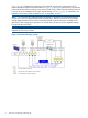
Figure 1 (page 8) illustrates a local array and an external array that are connected using XP External Storage and Fibre Channel hardware. In Figure 1 (page 8), the external array is connected to the external port of the local array via a switch (or hub) using a Fibre Channel interface. External is a local array port attribute used for XP External Storage. In Figure 1 (page 8), external LUs are mapped as local array VDEVs and LDEVs and, consequently, as an LU.
2 Preparing for XP External Storage operations This chapter describes requirements, preparations, and notes for XP External Storage. This chapter also describes the HP products you can use with XP External Storage.
• XP Command View Advanced Edition Software (running on a user-supplied Windows®-based PC) or Remote Web Console For instructions on installing and using XP Command View Advanced Edition Software or Remote Web Console, see the HP XP Command View Advanced Edition Software user guide for XP Disk Arrays or the HP XP Remote Web Console user guide for XP12000/XP10000 Disk Arrays and SVS 200.
Table 1 Storage arrays that can be connected as external arrays (continued) Storage array Notes HP XP12000 Disk Array • In XP External Storage panes, the array is a “12000”. • Alternate paths are in Multi mode (meaning that dynamic load balancing across multiple active paths is enabled). HP XP10000 Disk Array • In XP External Storage panes, the array is a “10000”. • Alternate paths are in Multi mode.
Table 1 Storage arrays that can be connected as external arrays (continued) Storage array Notes HP 200 Storage Virtualization System • In XP External Storage panes, the array is an “SVS200”. • Alternate paths are in Multi mode. HP 3000/5000 Enterprise Virtual Array (Active/Standby and Active/Active controllers) or HP 4000/6000/8000 Enterprise Virtual Array (Active/Active controllers) • In this user guide, the arrays appear as “EVA array”. • In XP External Storage panes, the arrays appear as “EVA”.
Table 1 Storage arrays that can be connected as external arrays (continued) Storage array Notes • In this user guide, the arrays appear as “Lightning 9900 subsystem”. • In XP External Storage panes, the Lightning 9910 is a “0401”, and the Lightning 9960 is a “0400”. • Alternate paths are in Multi mode. Virtual Storage Platform VP9500 subsystem XP External Storage Software panes, the array is “P9500”. Alternate paths are in Multi mode.
Table 1 Storage arrays that can be connected as external arrays (continued) Storage array Notes A/H-6593 subsystem • In XP External Storage panes, the array is a “300”. • Alternate paths are in Multi mode. SANRISE Universal Storage Platform subsystem • In this user guide, the array is a “SANRISE USP subsystem”. • In XP External Storage panes, the array is a “USP”. • Alternate paths are in Multi mode.
Table 1 Storage arrays that can be connected as external arrays (continued) Storage array Notes SANRISE H1024/H128 subsystem • In XP External Storage panes, the arrays appear as “1024” and “128”, respectively. • Alternate paths are in Multi mode. SANRISE H512/H48 subsystem • In XP External Storage panes, the arrays appear as “512” and “48”, respectively. • Alternate paths are in Multi mode. SANRISE H256 subsystem • In XP External Storage panes, the array is a “256”.
Table 2 XP External Storage requirements (continued) Item Requirement Maximum number of external LUs that can be connected • For the XP12000, 15,360 volumes can be connected • For the XP10000/SVS200, 8,192 volumes can be connected • 1,024 volumes can be connected per port NOTE: If you use HP XP Snapshot Software, the number of external LUs that can be connected is as follows: • For the XP12000: Number of external LUs + Number of virtual LUs 15,360 • For the XP10000/SVS200: Number of external LUs + Numb
Each item above is explained in the following sections. External ports Local array ports used for XP External Storage must be set to a designation of External. When the external array is connected to the local array's external port via Fibre Channel, you can view information about the external array from XP Command View Advanced Edition Software or Remote Web Console. The external array can be connected only to ports designated as External.
The following are the external LU's attributes: • Emulation type Set the mapped LU's emulation type by selecting any emulation type from the drop-down list. However, if you plan to use the mapped LU for XP Flex Copy operations, or you plan to access existing data in the external LU, you must select the OPEN-V emulation type to avoid data resizing. If you plan to use existing data in the external LU from the local array after mapping, you must select the OPEN-V emulation type.
NOTE: • When you set the cache mode, note the following: ◦ Data that is not written by the host (for example, data written by XP Business Copy Software) is asynchronously destaged to the external array regardless of the Cache Mode setting. ◦ If you set the emulation type for a mainframe system (such as 3390-x), data that is written by a host using a command such as Format Write is asynchronously destaged to the external array regardless of the Cache Mode setting.
Example of an alternate path configuration Figure 2 (page 20) shows an example of an alternate path configuration. In Figure 2 (page 20), external array ports WWN A and WWN B are connected to CL1-A and CL2-A, respectively, which are designated as external ports in the local array. You must specify the port of a different cluster in the local array for the alternate path, as ports CL1 and CL2 are specified in the figure.
Figure 4 Example of incorrect alternate path configurations Examples of switching I/O execution paths to alternate paths There are two alternate path modes: Single mode and Multi mode. This section describes examples of the performance when the I/O execution path switches to the alternate path for each path mode as follows: • Alternate path mode is Multi mode. • Alternate path mode is Single mode. • Alternate path mode is Single mode and at least one alternate path is in Standby status.
Figure 5 Alternate path mode is Multi mode Note: In Multi mode, active I/O load balancing occurs across external array ports and controllers. The XP and EMC DMX are examples of external arrays that use Multi mode. • Alternate path mode is Single mode. Figure 6 (page 23) shows an example of when the alternate path mode is Single mode. When an error occurs in the path used for I/Os, the I/O execution path switches to the path with the second highest priority.
Figure 6 Alternate path mode is Single mode • Alternate path mode is Single mode and at least one alternate path is in Standby status. Figure 7 (page 24) shows an example of when the alternate path mode is Single mode and there are alternate paths in Normal and Standby status. Figure 8 (page 24) shows another example of when the alternate path mode is Single mode. In Figure 8 (page 24), there are alternate paths in Standby status only.
Figure 7 Alternate path mode is Single mode with alternate paths in Normal and Standby Figure 8 Alternate path mode is Single mode with alternate paths in Standby only 24 Preparing for XP External Storage operations
Powering arrays on or off This section describes procedures for powering local and external arrays on or off after XP External Storage operations have started.
Powering local arrays on or off To power local arrays off CAUTION: When you want to turn off both the local array and the external array, you first need turn off the local array, and then turn off the external array. 1. 2. 3. Stop read and write I/Os to the external LU that is mapped as a local array internal LDEV. Perform other operations required before powering the local array off. Turn the local array's power off.
2. Execute the Check Paths & Restore Vol. command. For instructions, see Checking the connection status and resuming external LU operations (Check Paths & Restore Vol.). CAUTION: When powering the external array off after executing the Disconnect Subsystem command, you cannot access the mapped external LU from the local array when you initially turn on the external array. You must execute the Check Paths & Restore Vol. command to resume using the mapped external LU. The Check Paths & Restore Vol.
Writing new data to mapped external LUs Figure 9 (page 28) shows an example of writing new data in the mapped external LU from the host connected to the local array. 1. Use the XP External Storage GUI to map the LU in the external array as an internal LDEV of the local array. CAUTION: Set the IO Suppression mode to Disable. You can select the mapped volume's emulation type as required. If you select an emulation type for an open-system (such as OPEN-V), go to step 2.
Using existing data in mapped external LUs Figure 10 (page 29) shows an example of using existing data in a mapped external LU from the host connected to the local array. 1. From the host connected to the external array, write data to the LU in the external array. 2. Use XP External Storage to map the LU in the external array containing data as an internal LDEV of the local array.
1. Log in to XP Command View Advanced Edition Software or Remote Web Console. For instructions, see the HP XP Command View Advanced Edition Software user guide for XP Disk Arrays or the HP XP Remote Web Console user guide for XP12000/XP10000 Disk Arrays and SVS 200. 2. 3. 4. Click the XP External Storage button ( ). XP External Storage starts. Cancel any existing Flex Copy pairs. For instructions, see the HP Flex Copy XP user guide. Delete any external LU mapping.
• When a port in an external array connected to XP12000 Disk Array has a management LU (for example, Universal Xport LU) that stores control information from a particular application, note the following: ◦ A management LU cannot be used as an external volume. A management LU in this document means an LU that receives commands issued by a particular application and that controls or manages the application. A command device is not a management LU.
• If you map an external LU that is equal to or greater than 695.98 GB with a 3390 mainframe emulation type, you can access data stored in the field up to 695.98 GB. You cannot access data stored in the field over 695.98 GB. However, for emulation types with a small base capacity, some of the field of 695.98 GB might not be available. For more information, see “Required volume capacity for emulation types” (page 160).
Figure 13 External LU capacity is smaller than the specified emulation type's basic capacity • IO Suppression mode can only be selected when the volume being mapped is set to the OPEN-V emulation type. If a different emulation type is set, IO Suppression mode is automatically set to Disable. • If you use the mapped external LU from the host connected to the local array, set the IO Suppression mode to Disable when mapping the LU. For XP External Storage, select Disable. For XP Flex Copy, select Enable.
If you format the external array's mapped LU from the external array side, data that existed prior to formatting cannot be ensured. When using the mapped external LU from the mainframe OS, format the mapped volume from the local array side. 34 • IO Suppression mode is set when the LU is mapped and it cannot be changed while the LU is mapped. To change IO Suppression mode, delete the external LU mapping (Delete LU operation), and remap the LU with different attributes (Add LU operation).
• Operations cannot be performed if some parts of the local array are blocked. In this case, restore blocked parts of the local array, and retry the operation. • When using the Thunder 9500V series subsystem as an external array, the following versions are recommended. If you use a 9500V array with a version that is earlier than the following versions, the SATA drive information might not display correctly.
• You cannot execute the Disconnect Subsystem or Disconnect Volume command for external LUs that include LDEVs set as copy pairs for XP Flex Copy, XP Business Copy, Hitachi ShadowImage for z/OS, XP Continuous Access Journal, Hitachi Universal Replicator for z/OS, XP Continuous Access, Hitachi TrueCopy for z/OS, or XP Snapshot. However, these commands can be executed in one of the following cases: ◦ When the XP Business Copy pair status is PSUE ◦ When the ShadowImage for z/OS™ pair status is Suspend.
Table 4 When external LU's emulation type is for mainframes Application HDD type FC SATA Not Recommended Not Recommended Not Recommended Not Recommended Operation from TPF Not Supported Not Supported File operation from host OK Not Recommended OK OK Backup OK Recommended Archive OK Recommended Database Online Transaction Processing (OLTP) System volumes (Journal, Check points) (both Read and Write) File operation from host (mainly Read) • The external array's performance and status a
The following sections provide configuration examples for specific HP software products: • Using external LUs for Auto LUN XP operations • Using external LUs for Continuous Access XP operations • Using external LUs for Continuous Access XP Journal operations • Using external LUs for Business Copy XP operations • Using external LUs for Snapshot XP operations The following HP software products support the use of mapped external LUs.
• XP Continuous Access (Synchronous and Asynchronous) You must set the IO Suppression mode to Disable to use the mapped external LU for XP Continuous Access operations. For an XP Continuous Access configuration example, see Using external LUs for Continuous Access XP operations. • Hitachi TrueCopy for z/OS You must set the IO Suppression mode to Disable to use the mapped external LU for Hitachi TrueCopy for z/OS operations.
• SNMP Information about the mapped external LU and external port is displayed. • Configuration File Loader ◦ You can set the path definition for external LUs (add, delete, or change paths). ◦ You can set the command devices on external LUs (add or delete the setting). ◦ CHIP mode, host group, and WWN settings for external ports are not supported. When an external LU is mapped through that external port, the topology setting is not available.
2. Prepare a local array internal LDEV with the same capacity as the mapped external LU. Use Volume Manager to adjust the internal LDEV's capacity as required. For instructions, see the HP XP LUN Configuration and Security Manager user guide: HP XP12000 Disk Array, HP XP10000 Disk Array, HP 200 Storage Virtualization System. CAUTION: 3. 4. The emulation type of the local array's prepared internal LDEV must be OPEN-V.
user guide: HP XP12000 Disk Array, HP XP10000 Disk Array, HP 200 Storage Virtualization System. Go to step 4. 3. If you set a mainframe-system emulation type when mapping the volume, the mapped volume's status becomes Blockade. To format the volume, use the CVS function. To restore the volume, perform the Write to Control Blocks operation if you mapped a volume for which the data area has already been zero-formatted on the external array side.
2. If you set an open-system emulation type when mapping the volume, the mapped volume's status automatically becomes Normal. However, the volume-formatting process is not automatically executed. To optionally format the mapped volume, use the Custom Volume Size (CVS) function. For instructions, see the HP XP LUN Configuration and Security Manager user guide: HP XP12000 Disk Array, HP XP10000 Disk Array, HP 200 Storage Virtualization System. Go to step 4. 3.
user guide: HP XP12000 Disk Array, HP XP10000 Disk Array, HP 200 Storage Virtualization Systemr. Go to step 4. 3. If you set a mainframe-system emulation type when mapping the volume, the mapped volume's status becomes Blockade. To format the volume, use the CVS function. To restore the volume, perform the Write to Control Blocks operation if you mapped a volume for which the data area has already been zero-formatted on the external array side.
4. Set the XP Snapshot pair's P-VOL and S-VOL specifying the pool you created in step 3.
3 Managing cache with external storage XP disk arrays and storage virtualization systems use cache to facilitate host and internal I/O. When cache mode is enabled, host I/O is accepted as quickly as it is received into the array's cache where the associated read or write is buffered. When cache mode is disabled, the array limits caching to one block of read and write data per LDEV.
Determining, setting, or changing the external LU cache mode You set the cache mode when you define external LUs. HP strongly recommends that you set cache mode to Disabled for external LUs. For instructions on mapping external LUs in a new configuration, see Mapping external LUs (Add LU). CAUTION: Before you delete any LUs that you want to remap, carefully record necessary configuration information.
Collecting device information Before you remap an external storage device, collect the following information for each device: • LU number in the group • Universal Unique ID (UUID) • Path settings • CVS settings • Mapped location • External group number • CU:LDEV identifier To collect each of these items: 1. In the Remote Web Console main pane, click the External Storage button in the left pane. The LU Operation pane appears. 2.
Figure 21 LU Operation pane, Path Setting option Determining, setting, or changing the external LU cache mode 49
The Path Setting pane appears (Figure 22 (page 50)). Figure 22 Path Setting pane 4. To find the CVS settings, mapped location, external group number, and CU:LDEV identifier, right-click the LDEV in the Device list on the LU Operation pane, and select LDEV Information (Figure 21 (page 49)). The LDEV Information pane appears (Figure 23 (page 50)).
Deleting and remapping the external LU You must delete and remap each LU that needs the cache setting changed. Using the information recorded in Collecting device information, delete and remap each LDEV. 1. On the LU Operation pane, select the appropriate external LU group number in the Device tree. 2. In the Device list, right-click the external LU that you want to delete, and select Delete LU (Figure 21 (page 49)). 3. Click Apply. 4. Click either Yes or No. If you click Yes, skip the next step. 5.
Cache can be partitioned for Company B as follows: • CLPR0: 12 GB for the internal XP12000 P-VOL • CLPR1: 4 GB for the EVA S-VOL and P-VOL • CLPR2: 4 GB for the MSA S-VOL • All external LU cache is disabled To partition cache for external storage: 1. Determine the number and size of the partitions you need (see Determining the number and size of needed partitions). 2. Create the partitions (see Creating cache partitions).
Figure 24 Partition Definition pane 5. 6. Click Apply for the changes to becomes effective. Repeat step 3 through step 5 to define any additional CLPRs that you need.
7. To allocate external storage groups to a CLPR: a. Double-click the SLPR. b. Select the CLPR that you want to assign the external storage groups from (this will be CLPR0 if this is the first time you are configuring partitioning). c. Select and right-click the external storage groups that you want to assign to another CLPR, and then select Cut (Figure 25 (page 54)). Figure 25 Partition Definition pane, Cut option d.
e. f. Click Apply. Repeat step 7b through step 7e until you have allocated the external storage groups to the appropriate CLPRs according to the plan you created after reading Partitioning cache for external storage. For complete information about creating SLPRs and CLPRs, see the HP XP Disk/Cache Partition user guide for XP12000/XP10000 Disk Arrays and SVS 200. Changing storage system modes In addition to cache partitioning and cache modes, array system modes control LU cache usage.
4 XP External Storage panes XP External Storage operations involve the LU Operation and Port Operation panes. In addition to these two panes, the Flex Copy pane is available if you licensed XP Flex Copy. When you select a tab, the corresponding pane appears. Figure 27 Panes for XP External Storage operations LU Operation pane This pane appears when you start XP External Storage. Information about the external array appears on the LU Operation pane.
Figure 28 LU Operation pane • Device, WWN, and Port trees Displays information in the Device, WWN, or Port list depending on the item selected in the tree. Select the tab to display a tree. The following items can be selected in each tree: • ◦ Items you can select in the Device tree include Subsystem (local XP), External Devices (arrays), product names of connected external arrays, external LU group numbers, Discovery, and external array WWNs. For more information, see Device tree.
• Information area Displays information about the contents of the Device, WWN, or Port list, including: ◦ Total number of Devices: Number of external LUs that are connected. ◦ Total number of External Groups: Number of external LU groups that are set. ◦ Total number of External LUs: Number of external LUs that are connected. ◦ Found WWNs: WWNs found when you clicked Discovery in the Device tree.
Figure 29 Device tree The Device list (right pane) changes according to the item selected in the Device tree. • Subsystem When selected, displays nothing in the Device list and displays the External Devices branch of the tree. Subsystem is selected when you start XP External Storage and display the Device tree. • External Devices When selected, the Device list displays information about external arrays connected to external ports that have been detected (supported).
Figure 30 Device list (external device selected in Device tree) Following items are displayed in the Device list. The displayed contents differ depending on the items selected in the Device tree. The items displayed in the Device list are described below on each item selected in the Device tree. • Subsystem Displays nothing. Subsystem is automatically selected when you select the Device tree.
Table 8 Mapped external LU status values • • LDEV status Description Normal LDEV status is normal. Unknown LDEV status has yet to be ascertained. Blockade I/O traffic to the LDEV is not permitted. Warning External LUs have abnormal status. Format Volume is in the process of being formatted. Product name of the connected external array ◦ ExG: External LU group number. This appears when you group the LUs from one or more external arrays under a common number. ◦ Serial: Product serial number.
• • ◦ Ex-Dev. Status: Status of the operation executed to the external array, or status of the path connection. Possible values: Normal, Unknown, Blockade, Warning, Checking, Cache Destage, and Disconnect. For a description of these values, see Table 7 (page 60). ◦ LDEV Status: Mapped external LU's status. Possible values: Normal, Unknown, Blockade, Warning, and Format. For a description of these values, see Table 8 (page 61).
Figure 31 WWN tree • Subsystem When selected, displays nothing in the WWN tree. Subsystem is selected when you initially display the WWN tree. • External Devices When selected, displays information about the external array connected to the external port in the WWN list. • Product name of the connected external array When selected, displays the name of the external array for which the connection setting is already completed in the tree under External Devices.
Following items are displayed in the WWN list. The displayed contents differ depending on the items selected in the WWN tree. The items displayed in the WWN list are described below on each item selected in the WWN tree. • Subsystem When selected, displays nothing in the WWN tree. Subsystem is selected when you initially display the WWN tree. • • External Devices ◦ Serial: Product serial number. ◦ Product: Product name. ◦ Vendor: Vendor name. ◦ Ex-Dev.
• – Warning: There are paths whose status is not normal. Check the status of the paths. – Checking: Process of checking the paths' defined configuration informations is in progress. WWN of the external array ◦ Port: Port number of the local array connected to the port identified by the WWN selected in the Port tree. One of the following icons appears for each port: Icon Description Port in Standard mode. Port in Initiator/External MIX mode.
◦ – Standby: The port of the external subsystem is standing by. The port status is normal but cannot receive I/O. – Target error: Port failures, such as controller blockade are detected on the external subsystem side. – Checking: Process of checking the paths' defined configuration information is in progress. – Disconnect: Connection to the external array or external LU was intentionally stopped using the Disconnect Subsystem or Disconnect Volume command.
The items displayed in the Port tree and the contents displayed in the Port list when you select each item are as follows. • Subsystem When selected, displays nothing in the Port list. Subsystem is selected when you initially display the Port tree. • External When selected, displays information about the port whose port attribute is set to External in the Port list. • Local array port number When selected, displays connection information about the selected port in the Port list.
The displayed contents changes depending on the item selected in the Port tree. • Subsystem When selected, displays nothing in the Port tree. Subsystem is selected when you initially display the Port tree. • External ◦ Port: Port of the local array with the port attribute is set to External. One of the following icons appears for each port: Icon Description Port in Standard mode. Port in Initiator/External MIX mode. • ◦ Path: Number of set paths.
◦ WWN: WWN identifying the external array's port. This port is connected to the local array port selected in the Port tree. ◦ LUN: External array's LU number. ◦ Characteristic: External LU's identification number. ◦ Group: External LU group number and reference number assigned to each LU in the external LU group. XP External Storage automatically assigns the reference numbers to LUs in the group when the external LUs are mapped.
status becomes Backoff, the primary path does not changed to the alternate path immediately. After the error recovery, the status becomes Normal. If the status cannot be recovered from the error, the path status changes to the other status. ◦ Characteristic2: External LU's extended identifying information. This information is used for identifying logical volumes in the EVA array. For more information, see Identifying logical volumes of EVA arrays (using Characteristic 2).
Figure 36 Preset Detail window (mapping operation) • Delete Cancels settings selected in the Preset list. Port Operation pane Use this pane to check port settings and set port attributes. This section describes items displayed in the Port Operation pane. For instructions, see Setting a local array's port attributes. Figure 37 Port Operation pane • Port Operation tree Displays information about the selected port in the Port list (right pane). You can select Subsystem, a port attribute, or a port number.
• Information area Displays the total number of ports currently displayed in the Port Operation list (Total Number of Ports). • Preset list Displays rows corresponding to the ports that are about to be acted upon. The contents displayed in the Preset list have not been applied to the local array yet. When you click Apply on the Port Operation pane, actions designated in the Preset list are applied to the local array. For more information, see Preset list (Port Operation pane).
• Target When selected, displays ports designated as host target ports (used for host connect). • RCU Target When selected, displays ports designated as an RCU target (receiving) port (used for XP Continuous Access, Hitachi TrueCopy for z/OS, XP Continuous Access Journal, Hitachi Universal Replicator for z/OS, and so on). • Initiator/External When selected, displays ports for which the Initiator/External MIX mode is set.
• Attribute Port attribute. External ports are used for connecting to the external array. To set a remote command device, you can use the port for which the Initiator/External MIX mode has been set. • PCB Mode Port's PCB mode. Standard, High Speed, or MIX (for Initiator/External MIX mode) appears. External ports do not have High Speed mode.
5 Configuring external LUs Use XP External Storage to perform operations to access external LUs, such as setting the port attribute to the external port and mapping the external LU as the internal LDEV. This chapter describes procedures for using XP External Storage to configure external LUs.
Figure 41 Overview of configuring external LUs The following is the general procedure for configuring external LUs. 1. Configure the port and system parameters for the external array. For instructions, see the external LU's documentation, Setting an external array's port, and Notes on connecting external arrays. 2. Start XP External Storage operations.
9. Define alternate paths between the external array or mapped LU and the local array. For instructions, see Defining alternate paths. 10. Use XP LUN Configuration and Security Manager Software to define paths. For instructions, see the HP XP LUN Configuration and Security Manager user guide: HP XP12000 Disk Array, HP XP10000 Disk Array, HP 200 Storage Virtualization System. Setting an external array's port This section describes the procedure for setting the external array's port.
Discovering and Mapping LUs After setting the port used for XP External Storage to External, map the external LU as an internal LDEV. If you mapped the external LU and previously set the VMA of XP LUN Security Extension in that volume, the former VMA setting is overwritten when you map the volume again. However, if XP LUN Security Extension is not installed when you remap the volume, the volume with the VMA setting cannot be mapped.
• LUN LU number of the external LU. • Device External LU's device name. • Ex-Dev. info. External array information. When the external array is an XP1024/XP128 or TagmaStore Workgroup Modular Storage (WMS) array, an asterisk (*) appears. • VMA Information about the VMA setting of XP LUN Security Extension. If you mapped the external LU and previously set the VMA of XP LUN Security Extension, an asterisk (*) appears.
• IO Suppression Mapped external LU's IO Suppression mode (for OPEN-V emulation only) (see External LU attributes set by mapping). To suppress I/O operations from hosts (by way of the XP12000/XP10000/SVS200) to the mapped external LU or use the mapped external LU for a Flex Copy pair, select Enable. If you do not suppress I/O from hosts to the mapped external LU, select Disable (for example, for use with XP External Storage).
path, use the Select Paths pane to specify candidates for alternate paths. Alternate paths are automatically set from the candidates, as many as the number set in Alternate Path. CAUTION: If you do not set alternate paths on the Select Paths pane, alternate paths are automatically set according to the WWN selected in the Device tree on the LU Operation pane when you started the Add LU operation. • Clear button Resets all the external LU's attributes.
The OK button is available when mapping on the Add LU window is complete. • Cancel button Cancels all mapping operations, closes the Add LU window, and returns to the LU Operation pane. Select Paths pane All paths that can be set as primary and alternate paths appear in the Select Paths pane. To set a specific path as the alternate path, use the Select Paths pane to specify candidates for the alternate paths.
• Set button If you select the port (external array WWN) you want to set as the candidate for the primary and alternate paths in Unselected Paths, and click Set, the selected WWN moves to Selected Paths. • Release button If you select the port (external array WWN) you want to exclude from the list of candidates for the primary and alternate paths in Selected Paths, and click Release, the selected WWN moves to Unselected Paths. • OK button Saves settings in the Select Paths pane, and closes the pane.
j. Select one or more external LUs, and select one or more cells in the LDEV map. When selecting two or more external LUs in the CU:LDEV list, if you select one cell of the internal LDEV number in the LDEV map, the number of cells automatically selected is the same as the number external LUs selected in the CU:LDEV list with the selected internal LDEV first. When Interval is set, mapping is done at intervals of the specified number.
6. If you do not want to automatically set primary and alternate paths, but want to specify paths set as candidates for primary and alternate paths, click Select Paths. The Select Paths pane appears. To automatically set alternate paths, go to step 9. 7. 8. 9. Select the path and exclude it from the list of candidates for primary and alternate paths in the Select Paths pane. For more information, see Select Paths pane. Click OK. The Add LU pane appears.
the setting in the Preset list, and select Detail. To cancel settings, right-click the setting in the Preset list, and select Delete. Go to step 13. 10. If you need to set an SSID to the mapped internal LDEV, the SSID pane appears. When storage is partitioned using XP Disk/Cache Partition, select the SLPR number in the SLPR box. If you select the Limited check box and select the SLPR number, you can set only SSIDs that can be used for the selected the SLPR.
NOTE: If you set Interval for the mapping, the CU:LDEV number of the internal LDEV that must be mapped is set to the specified interval value. Use the Auto Map Setting and Select LDEV windows (Figure 49 (page 89)) for mapping multiple external LUs at one time. Figure 48 Auto Map Setting window • ExG (1-16384) Group number containing the specified external LU. Specify any decimal value from 1 to 16384. The E displayed outside of the text box is the capital letter of the external LU group.
If you do not suppress I/O from hosts to the mapped external LU, select Disable (for example, for XP External Storage). When setting the emulation type to something other than OPEN-V, I/O Suppression mode is automatically set to Disable. When the external LU to be mapped has the VMA setting, IO Suppression mode is automatically set to Disable.
• Select LDEV button Displays the Select LDEV window (Figure 49 (page 89)) where you can select the first CU:LDEV number in the series. • Select Paths button Displays the Select Paths pane (Figure 43 (page 82)). Use the Select Paths pane to select paths as candidates for primary and alternate paths and select paths not set to primary and alternate paths. By default, all paths with a confirmed connection status of normal are set as candidates for primary and alternate paths.
The Select LDEV pane consists of the following items. • CU list CU number of the local array to which you want to map the external LU. You can select the CU number from the drop-down list. • Interval Interval of the CU:LDEV number for mapping each volume. When two or more LDEVs are created from one external LU and mapped, the CU:LDEV number is set at intervals specified in each created LDEV. For example, set the interval as follows: ◦ In the Device list, select three external LUs.
NOTE: 6. 7. 8. 9. Attributes for all LUs mapped at one time are identical. • To select the first CU:LDEV number of the mapped destination internal LDEVs and the mapping interval, go to step 6. • To let XP External Storage select the first CU:LDEV number, go to step 9. Click Select LDEV. The Select LDEV window appears. Select the first CU:LDEV number of the mapped destination internal LDEVs and the mapping interval. Click OK. The Auto Map Setting window appears.
18. Click OK. The mapping set in the Auto Map Setting window is applied to the local array, and the specified contents appear in the Device list. When an error occurs during the external LU mapping process, the failed setting and an error code appears in the Preset list. To check the error message, right-click the failed setting, and select Detail.
• Reserved Indicates whether XP RAID Manager and XP Command View Advanced Edition Software or Remote Web Console can be used to make LU path and command device settings. • ◦ Hyphen (-): You can use XP RAID Manager and XP Command View Advanced Edition Software or Remote Web Console to make LU path and command device settings. ◦ RAID Manager: You can use XP RAID Manager to make LU path and command device settings, but cannot use XP Command View Advanced Edition Software or Remote Web Console.
• Canceling alternate path definitions • Changing alternate paths • “Replacing all the alternate paths with newly-added alternate paths” (page 99) The Path Setting window displays information about external arrays and the condition of paths set from the internal LDEV to the external LU. Figure 51 Path Setting window • Vendor External array's vendor. • Product External array's product name. • Serial External array's serial number.
• Alternate Path list Status of alternate paths. The Alternate Path list consists of two tables. The Configured Paths table displays previously defined paths. The Available Paths table displays available paths. The Alternate Path list displays the following information: ◦ Port: Port number in the local array connected to the external array. One of the following icons appears for each port: Icon Description Port in Standard mode. Port in Initiator/External MIX mode.
• – Disconnect: Connection to the external array or LU was stopped using the Disconnect Subsystem or Disconnect Volume command. – Unavailable: External array replied Unavailable. The external array demands to change the connected port. After the status becomes Unavailable, the primary path changes to the alternate path that is in the Standby status. When the primary path changes, the path status becomes Normal. – Backoff: External array replied Backoff.
3. In the Device list, right-click the external LU, and select Path Setting. The Path Setting window appears. The Configured Paths table displays detailed information about one currently defined path and the alternate paths. The Available Paths table displays paths that can be set as alternate paths. 4. In the Available Paths table, right-click the row of the path to be defined as an alternate path, and select Add.
Figure 52 Path Setting window, shortcut menu 6. Repeat the Priority Up command until the row of the selected path is displayed on the first line of the Configured Path list and that row's Priority column changes to 1. When the Priority column changes to 1, the path is set as the typically used one (primary path). 7. Click OK. The Path Setting window closes, and the LU Operation pane appears. Selected rows appear in blue italics in the Device list. Specified contents appear in the Preset list.
Changing alternate paths To change an alternate path, cancel the current alternate path, and then define another path as a new alternate path. CAUTION: You cannot delete all the current alternate paths to substitute newly-added alternate paths for them in one operation. To replace all the current alternate paths with newly-added alternate paths, you need to perform more than two operations and leave at least one current alternate path setting when you perform the first operation.
Figure 53 Overview of Operation to Replace All the Current Alternate Paths with Newly-added Alternate Paths To replace all the current alternate paths (A and B) with newly-added alternate paths (C and D): 1. Execute the Disconnect Paths command on the alternate path A (see 5.16). 2. Disconnect the cable which the alternate path A uses, and connect the cable which the alternate path C uses. 3. Cancel the configuration of the alternate path A, and add the alternate path C (see 5.5.4). 4.
Paths panel, check the setting on the Path Setting panel, and then apply the setting to the array. You can also change the setting of the paths by each external volume on the Path Setting panel. CAUTION: You cannot delete all the current alternate paths to substitute newly-added alternate paths for them in one operation.
• OK Saves settings in the Add Paths window, closes the Add Paths window, and displays the Path Setting window. • Cancel Cancels all settings in the Add Paths window, and closes the window. To add alternate paths to multiple external LUs at one time: 1. Select the LU Operation tab. The LU Operation pane appears. 2. In the Device tree, select an external LU group number. Information about external LUs mapped as internal LDEVs appears in the Device list. 3.
Figure 55 Delete Paths window • Port Local array ports. After selecting a port, you can add the paths. One of the following icons appears for each port: Icon Description Port in Standard mode. Port in Initiator/External MIX mode. • Selected Paths Paths of WWNs to be deleted. WWNs identify ports on the external array. Nothing is displayed when you first access the Delete Paths window.
5. 6. 7. 8. In the Unselected Paths list, select ports (WWNs of the external array), and click Set. The selected ports move to the Selected Paths list. Click OK. The Path Setting window appears. Ensure that deleted paths are applied to the array in the Path Setting window. You can also change the alternate path setting in this window. For more information, see Setting alternate paths for external LUs. Click OK. The Path Setting window closes, and the LU Operation pane appears.
Figure 56 LDEV Information window • Vendor External array's vendor. • Product External array's product name. • Serial External array's product serial number. • Group External LU group and reference number of the external LU in the group. • Characteristic External LU's identification number. • Device External LU's device name. • Capacity External LU's capacity. When the mapped external LU's emulation type is for open systems, capacity is displayed in 512-byte blocks.
• ◦ Capacity: External LU's capacity. ◦ Status: External LU's status. Possible values: Normal, Unknown, Blockade, Warning, and Format. Warning indicates that some alternate paths are blocked. Format indicates the external LU is currently being formatted. View all LUs Displays information about all external LUs in the LDEV list. • View all Volumes When the external LU is part of a LUSE volume, displays all LDEVs that make up the LUSE volume in the LDEV list.
5. In the LDEV list, right-click the row of the external LU to be restored, and select Restore. Figure 57 Shortcut menu of the LDEV Information window The Status column in the selected external LU row changes to Restore. 6. Click OK. The LDEV Information window closes, and the LU Operation pane appears. Specified contents appear in blue italics in the Device list and appear in the Preset list. To check setting details, right-click the setting in the Preset list, and select Detail.
Figure 58 Volume Detail window You can also check the LDEVs making up a LUSE volume by selecting View all Volumes at the bottom of the LDEV Information window. However, only LDEVs in the specified external LU appear. The Volume Detail window displays all LDEVs, including LDEVs of other external LUs. The Volume Detail command is available after you restore the external LU using the Restore command.
a mapped volume with the former settings. For instructions, see Checking the connection status and resuming external LU operations (Check Paths & Restore Vol.). CAUTION: • Note the following for the Disconnect Subsystem and Disconnect Volume commands: After executing the Disconnect Subsystem or Disconnect Volume command, click the Refresh button ( ) on the XP Command View Advanced Edition Software or Remote Web Console main pane to update the information, and check the current progress status.
Figure 59 Disconnect array and check paths and restore volume commands The selected external array appears in blue italics in the LU list and Device list, and appears in the Preset list. To check details on the intended operations, right-click the setting in the Preset list, and select Detail. To cancel settings, right-click the setting in the Preset list, and select Delete. 3. 4. Click Apply. A confirmation message appears. Click OK. The Ex-Dev.
4. Click OK. The Ex-Dev.Status column in the Device list changes to Cache Destaging. When XP External Storage finishes writing data from cache to the external LU, the Ex-Dev. Status column changes to Disconnect. If errors occur during disconnect operations, failed operations and error codes appear in the Preset list. To check error messages, right-click the failed operation row, and select Detail.
4. Click OK. The path status in the Path Setting pane changes to Checking. When XP External Storage finishes checking path status and the external array can be restored, the Status column changes to Normal. If the external array cannot be restored, the status changes to Blockade. Restoring external LUs individually (Check Paths & Restore Vol.) 1. 2. In the LU Operation pane, select an external LU group number in the Device tree.
4. Click OK. For the external LUs of the selected external array, the Status column of the Device list changes to the restored status, and the external LU can be used in XP Command View Advanced Edition Software or Remote Web Console. When errors occur during a status change for the external LU, the failed setting and error code appears in the Preset list. To check the error message, right-click the failed setting, and select Detail. Restoring volumes in a mapped external LU individually 1. 2.
Changing the cache mode of all external LUs in an external array The procedure to change the cache mode of all external volumes in an external array is as follows: 1. Log on to Remote Web Console. 2. 3. 4. 5. 6. 7. 8. Click the XP External Storage icon ( ) on the Remote Web Console main pane. The XP External Storage pane (LU Operation pane) is displayed. Change the session to Modify mode by clicking the modify icon.
Stopping the use of paths to an external LU by specifying an external array's WWN (Disconnect Paths) To stop using the path between the local array and the external array by specifying the WWN that identifies the external array's port, select the WWN tree to display the WWN list. NOTE: The Disconnect Paths command is not for the actual disconnection of the path to the external LU.
Changing an external array's port setting You can change the setting of an external array's port by specifying the WWN that identifies the external array's port in the WWN list. Use the Change Parameter pane (Figure 60 (page 116)) to change the port setting. Figure 60 Change Parameter pane • IO TOV (10-240): Timeout value for the I/O to the external LU. The value can be 10 to 240 (in second). The default value is 15.
Stopping the use of paths to an external LU by specifying a local array's port (Disconnect Paths) To stop using the path between the local array and external array by specifying the port of the local array, select the Port Operation tree. The Port Operation list appears. 1. In the LU Operation pane, select the Port Operation tab. The Port Operation tree and Port Operation list appear. 2. In the Port Operation tree, select External (the port attribute for the external array connection).
Before deleting the external LU mapping, notice if any of the following are true: • Whether or not the execution of any application (for example, XP RAID Manager) that is using the command device is in progress. If any application using an external LU command device is executing, stop the application. • Whether the Disconnect Subsystem or Disconnect Volumes command was executed.
6 Troubleshooting NAS Blade systems that include external arrays If your local array is provided with a NAS package, you can configure the NAS Blade system that includes an external array. This chapter describes procedures to stop the external array for maintenance and recover the external array from a failure.
Figure 61 Example of a NAS Blade system configuration that includes an external array CAUTION: To stop the external array, execute the procedure according to the following description. If you execute the wrong procedure, an error occurs in the NAS Blade system (for example, the file system might be blocked or the resource group's status might become inappropriate). Stopping external arrays 1. 2. 3. 4. Stop access from the client. Stop the cluster using NAS Blade Manager.
3. 4. 5. Execute the Check Paths & Restore Vol. command using XP External Storage to restore the path to the external array. For instructions, see Checking the connection status and resuming external LU operations (Check Paths & Restore Vol.). Confirm that the connection between the local array and the external array is normal. Start NAS OS 1 (NAS channel adapter's OS) and NAS OS 2 using XP LUN Configuration and Security Manager Software. NOTE: The NAS OS can also be started from the SVP.
Figure 62 Error in an external array's disk 1. 2. Delete all XP Business Copy or XP Continuous Access pairs, if you created pairs. Perform the following operations on node 1: a. Release the differential-data storage device using NAS Sync Image. b. Delete the NFS share, CIFS share, and file system using NAS Blade Manager. 3. Change resource group 1's execution node to node 2 using NAS Blade Manager (failover). If resource group 1's status is Offline, this operation is not required. 4. 5. 6. 7.
13. Perform one of the following operations using NAS Blade Manager: • When resource group 2's status is Online, change resource group 2's execution node to node 2 (failback). • When resource group 2's status is Offline, start resource group 2. 14. Change the error disk in the external array to restore the external array's status. 15. Execute the Check Paths & Restore Vol. command using XP External Storage.
1. 2. 3. Restore (for example, check the cable's connection status or change the switch) the status of the error path between the local array and external array 1. Execute the Check Paths & Restore Vol. command using XP External Storage. For instructions, see Checking the connection status and resuming external LU operations (Check Paths & Restore Vol.). Change resource group 1's execution node to node 2 using NAS Blade Manager (failover).
• Clients cannot access volumes in external array 1, but can access volumes in external array 2. • The local array recognizes that the status of all file systems and volumes in external array 1 are blocked. Figure 64 Error occurs on the path to the external array used for node 1 1. 2. 3. 4. 5. 6. 7. 8. Restore (for example, check the cable's connection status or change the switch) the status of the error path between the local array and external array 1. Execute the Check Paths & Restore Vol.
is set between the local array and external array. In this case, if an error occurs in the only set path, none of the volumes in the external array can be used. NOTE: In the configuration in Figure 65 (page 126), HP recommends setting alternate paths to prevent the NAS Blade system from being blocked because of the path failure. For more information, see Alternate paths. The situation in Figure 65 (page 126) is as follows: • None of the user LUs can be used from node 1 or node 2.
7 Remote command devices This chapter describes remote command devices. • Overview of remote command devices • Notices about remote command devices • Mapping command devices as remote command devices • Using Continuous Access XP or Continuous Access XP Journal with remote command devices Overview of remote command devices A remote command device is a device in the local array to which a command device in the external array is mapped.
Notices about remote command devices • You can map command devices as remote command devices when one of the following arrays is connected as an external array: ◦ Virtual Storage Platform subsystem ◦ Universal Storage Platform V subsystem ◦ Universal Storage Platform VM subsystem ◦ XP12000 Disk Array ◦ XP10000 Disk Array ◦ HP 200 Storage Virtualization System ◦ XP1024/XP128 Disk Array ◦ TagmaStore™ Universal Storage Platform subsystem ◦ TagmaStore™ Network Storage Controller subsystem ◦
Table 9 Information displayed in the Device column for remote command devices (continued) Storage array Information displayed in Device column of Device list Universal Storage Platform V subsystem Example: OPEN-V-CM, OPEN-3-CM Universal Storage Platform VM subsystem XP12000 Disk Array XP10000 Disk Array HP 200 Storage Virtualization System XP1024/XP128 Disk Array TagmaStore™ Universal Storage Platform subsystem TagmaStore™ Network Storage Controller subsystem Virtual Storage Platform VP9500 subsystem H2
• The following are restrictions for mapping command devices as remote command devices. Table 10 Restrictions on remote command devices Item Restriction Emulation type OPEN-V Number of LDEVs in an external LU 1 IO Suppression mode Disable Cache mode Disable Minimum capacity 96,000 blocks (about 47 MB) Maximum capacity 2 TB • XP External Storage's Discovery operation cannot identify remote command devices.
Figure 67 (page 131) shows the difference between Standard and Initiator/External MIX modes. When ports are set to Standard modes, you must connect the cables for the initiator and external ports. However, if you set the Initiator/External MIX mode, you must connect only one cable, and you can use that path to operate XP Continuous Access or XP Continuous Access Journal and the remote command device.
Figure 68 Using XP Continuous Access or XP Continuous Access Journal with remote command devices Using Initiator/External MIX mode This section describes the procedure to use Initiator/External MIX mode and the procedure to stop using Initiator/External MIX mode. To use Initiator/External MIX mode: 1. Prepare the initiator ports of the Standard mode and external ports of the Standard mode in one port block.
2. 3. 4. Stop accessing the remote command device. Delete the remote command device mapping. Change the port block setting from Initiator/External MIX mode to Standard mode. For the procedure to change the port block setting, see the HP XP LUN Configuration and Security Manager user guide: HP XP12000 Disk Array, HP XP10000 Disk Array, HP 200 Storage Virtualization System.
8 Troubleshooting XP External Storage If you have a problem with the XP Command View Advanced Edition Software computer or XP Command View Advanced Edition Software or Remote Web Console software, see the HP XP Command View Advanced Edition Software user guide for XP Disk Arrays or the HP XP Remote Web Console user guide for XP12000/XP10000 Disk Arrays and SVS 200 for troubleshooting information. For additional assistance, contact your HP account support representative.
Table 11 General XP External Storage troubleshooting (continued) Error Corrective action Corrective action: The path status cannot be identified. Contact your HP account support representative. Blockade Status: The external port is blocked. Corrective action: The external port is blocked because of the microcode or package replacement or some other factor. Check the local array's status. If you cannot restore the path, contact your HP account support representative.
Table 11 General XP External Storage troubleshooting (continued) Error Corrective action Busy Status: The external array's status is BUSY. Corrective action: The external array's port is still recognized. Check the external array's settings and the load on the external array (for example, check whether the configuration assigns too much load on the external array). If you cannot restore the path, contact your HP account support representative.
Table 11 General XP External Storage troubleshooting (continued) Error Corrective action the external array. The following are possible causes: • The fibre cable is not connected properly. • The topology setting between the external and target ports does not match. • Because security is set on the port, the external array's device cannot be recognized from the local array. • If the external array is connected through switches, the switches' settings might not be appropriate.
Table 11 General XP External Storage troubleshooting (continued) Error Corrective action Even if the primary path's status becomes Backoff, the primary path does not change to the alternate path immediately. After error recovery, the status becomes Normal. Corrective action: If you cannot recover the status from the error, the path status changes to another status. Take the corrective action for the new path status. If you cannot restore the path, contact your HP account support representative.
Table 11 General XP External Storage troubleshooting (continued) Error Corrective action The Disconnect Subsystem or Disconnect ) on the XP Command View Advanced Edition Software or Remote Volume command has executed, but the Click Refresh ( progress status information is not updated. Web Console pane to update the displayed information. If the progress information for the Cache Destage status is not updated, even though you updated the information contact your HP account support representative.
9 Support and other resources Related documentation The following documents provide related information: • HP XP glossary • HP XP Snapshot XP user guide: HP XP12000 Disk Array, HP XP10000 Disk Array, HP 200 Storage Virtualization System • HP XP Auto LUN user guide: HP XP12000 Disk Array, HP XP10000 Disk Array • HP Business Copy XP user guide for XP128/XP1024 Disk Arrays • HP Cache LUN XP user guide for XP1024/XP128 Disk Arrays • HP XP Continuous Access Journal user guide: HP XP12000 Disk Array, H
HP websites For additional information, see the following HP websites: • http://www.hp.com • http://www.hp.com/go/storage • http://www.hp.com/support/manuals • http://www.hp.com/storage/spock Documentation feedback HP welcomes your feedback. To make comments and suggestions about product documentation, send a message to storagedocs.Feedback@hp.com. All submissions become the property of HP.
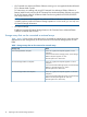
A Notes on connecting external arrays Connecting Thunder 9500V subsystems System parameters for connecting Thunder 9500V subsystems Table 12 (page 142) explains whether to specify system parameters when making settings for ports on the Thunder 9500V subsystem.
Table 12 System parameter settings (Thunder 9500V subsystems) (continued) Pane name Host Connection Mode Parameter Parameter setting Write and verify mode Set this parameter to ON. Host Connection Mode 1 Set this parameter to Standard Mode. Host Connection Mode 2 Specify HISUP Mode. NOTE: Do not specify any other parameters. NOTE: When using the Thunder 9500V subsystem as an external array, the following versions are recommended.
Table 14 Relationship between ports' WWNs and controllers (Thunder 9500V subsystems) (continued) Model Controller Port's WWN XXXXXXXXXXXXXXX5 XXXXXXXXXXXXXXX6 XXXXXXXXXXXXXXX7 NOTE: In WWNs, X is an arbitrary number or character. Ports in the same apparatus have identical values. Path status and examples of recovery procedures (Thunder 9500V subsystems) Table 15 (page 144) shows examples of recovery procedures when the path status is not normal.
Table 15 Path status and examples of recovery procedures (Thunder 9500V subsystems) (continued) Path status Examples of recovery procedures Cannot detect port There is a problem with the connection to the external array. The following are possible causes: • The fibre cable is not connected properly. • The topology setting between the external and target ports does not match. • If the external array is connected through switches, the switches' settings might not be appropriate.
Table 16 System parameter settings (TagmaStore AMS and TagmaStore WMS subsystems) (continued) Pane name System Parameter Parameters Parameter setting RAM Microprogram Version You can either specify this parameter or omit specifying this parameter. Option You can either specify this parameter or omit specifying this parameter. Operation if the processor failure occurs Set this parameter to Reset of occurred. WEB Title You can either specify this parameter or omit specifying this parameter.
Table 18 (page 147) shows the relationship between the port's WWN and the controller.
Table 19 Path status and examples of recovery procedure (TagmaStore AMS and TagmaStore WMS subsystems) Path status Examples of recovery procedures External device setting changed XP LUN Configuration and Security Manager Software may have changed the LU paths' settings. Check the LU paths' settings. If the LU paths' settings changed, change the settings back to the ones used when the volume was mapped. Or use XP External Storage to perform the Delete LU operation, and perform the Add LU operation again.
Notes When Power Saving Feature is Used (For TagmaStore AMS Subsystem, TagmaStore WMS Subsystem) When the external disk array is TagmaStore AMS2500, AMS2300, or AMS2100 and the power saving feature is used, do not access the external volume which is spinning down from the host. When you access the external volume which is spinning down from the host, the state of the external volume becomes Blockade.
Table 20 Path Status and Examples of Recovery Procedure (For VSP Subsystem) (continued) Path Status Examples of Recovery Procedure The access attribute of the volume may have been changed by Data Retention Utility. Check the access attribute of the volume. If the volume is protected by the access attribute, release the protection. Cannot detect port There is a problem with connection to the external subsystem.
Table 21 Path status and examples of recovery procedure (for XP24000/XP20000 Disk Arrays) (continued) The access attribute of the volume may have been changed by Data Retention Utility. Check the access attribute of the volume. If the volume is protected by the access attribute, release the protection. Cannot detect port There is a problem with connection to the external array. The following are possible causes: • The fibre cable is not physically connected in the proper way.
Table 22 Path status and examples of recovery procedures (XP12000/XP10000 Disk Arrays) (continued) Path status Examples of recovery procedures Data Retention Utility may have changed the volume's access attribute. Check the volume's access attribute. If the volume is protected by the access attribute, release the protection. Response error The volume may have been set as a pair volume for data copy.
Table 23 Path status and examples of recovery procedures (XP1024/XP128 Disk Arrays) (continued) Path status Examples of recovery procedures perform the Delete LU operation, and perform the Add LU operation again. XP LUN Security Extension Software may have changed the volume's access attribute. Check the volume's access attribute. If the volume is protected by the access attribute, release the protection. Illegal request The volume may have been set as a pair volume for data copy.
Path status and examples of recovery procedures (XP512/XP48 Disk Arrays) “Path status and examples of recovery procedures (XP512/XP48 Disk Arrays)” (page 154) shows examples of recovery procedures when the path status is not normal. When the path status is not normal, see “Troubleshooting External Storage XP” (page 134) and this table to recover the path status. If you cannot restore the path, contact technical support.
NOTE: If you are using microcode that does not support the SVS200, the SVS200 is recognized as an XP12000 Disk Array. To recognize the connected external array as the SVS200, use the microcode version that supports the SVS200 (which is microcode version 50-07-0X-XX/XX or higher). If you used an earlier microcode version that does not support the SVS200 to map the SVS200 volumes, delete the mapping setting, and then change the microcode version to the one that supports the SVS200.
Table 25 Path status and examples of recovery procedures (SVS200) (continued) Path Status Examples of Recovery Procedure Cannot detect port There is a problem with connection to the external array. The following are possible causes: • The fibre cable is not physically connected properly. • The topology setting does not match between the external and target ports. • If the external array is connected through switches, the switches' settings might not be appropriate.
Figure 69 Configuration example for which logical volumes can only be identified by characteristic Alternate path's behavior when an EVA array is connected When an EVA array is connected, the alternate path's behavior differs depending on the EVA array's microcode version. If the array type is EVA3000/5000, the behavior of the alternate path differs between the EVA arrays of the microcode version 4.000 or later and the EVA subsystems of the earlier microcode versions.
the following table, see the manuals of the Sun StorageTek 2540 and set the parameters appropriately for the connecting configuration. Table 29 System parameter settings for connecting Sun StorageTek 2540 Parameter Parameter setting host type Windows 2K non Clustered DMP Alternate paths for connecting Sun StorageTek V2X2 If you connect a Sun StorageTek V2X2 as an external array, specify 0 for Alternate Path when you map external volumes.
Alternate Path Mode for Connecting IBM DS8000 Series The alternate path mode for an IBM DS8000 series is Single by default. The alternate path mode for all IBM DS8000 series connected as external Storage can be changed to Multi when System Option Mode 566 to ON. Please call the Support Center to arrange for this mode to be set to ON and activated. NOTE: This System Option Mode requires minimum Microcode Version 50-09-77-00/00 (or higher). This mode can be changed either to ON or OFF non-disruptively.
B Required volume capacity for emulation types When mapping an external LU as a local array internal LDEV, you must specify the mapped volume's emulation type. How to determine the required external volume capacity The capacity required for the LDEV to be mapped is the total capacity of the data area for storing actual user data and the control information area for storing control information.
Figure 70 LDEV capacity Figure 71 (page 161) shows how to determine the volume capacity using the example of the OPEN-3 case. Figure 71 Calculating LU capacity (OPEN-3 example) Capacity list for each emulation type This section explains the LDEV capacity and volume capacity for each emulation type in the units of blocks and cylinders. Table 35 (page 162) lists the minimum data area capacity, base data area capacity, and control information area capacity for each emulation type.
Table 35 LDEV capacity information for each emulation type Emulation type Minimum data area capacity Base data area capacity Control information area capacity blocks cylinders blocks cylinders blocks cylinders 3380-3 72,000 50 4,808,160 3,339 10,080 7 3380-3A 72,000 50 4,808,160 3,339 10,080 7 3380-3B 72,000 50 4,808,160 3,339 10,080 7 3380-3C 72,000 50 4,808,160 3,339 10,080 7 3380-K 72,000 50 3,823,200 2,655 10,080 7 3380-KA 72,000 50 3,823,200 2,655 10,080
Table 36 Volume capacity information for each emulation type Emulation type Base LDEV capacity (blocks) blocks Minimum LDEV capacity Maximum capacity of external Maximum (blocks) LU (blocks) number of cylinders blocks cylinders blocks cylinders LDEVs* 1 3380-3 4,818,240 3,346 82,080 57 1,207,933,920 838,843 250 3380-3A 4,818,240 3,346 82,080 57 1,207,933,920 838,843 250 3380-3B 4,818,240 3,346 82,080 57 1,207,933,920 838,843 250 3380-3C 4,818,240 3,346 82,080 57 1,207,933,920
C Adjusting volume capacity for copy pair setting When creating an XP Business Copy or XP Flex Copy pair, the S-VOL's capacity must be the same as the P VOL. To set a copy pair's desired volume, you might need to adjust the volume capacity. This section describes the procedure to adjust the volume capacity. Copying data from external arrays (using external LUs as P-VOLs) For A, B, and C in the following description, see Figure 72 (page 164). To adjust the volume capacity to create a pair: 1.
2. 3. Check the capacity of the internal LDEV (B) to which the external LU (A) is mapped. If the mapped internal LDEV's (B) capacity is not same as the copy source volume (C), use Volume Manager to create a CV with the same capacity as the copy source volume (C) out of volume (B). Create a copy pair.
Index A Add LU (Auto) operation, 86 Add LU operation, 83 Add LU window, 78 alternate paths adding to multiple external LUs, 100 canceling, 98 changing, 99 defining, 19, 93, 96 deleting to multiple external LUs, 102 EVA arrays, 157 LU Operation pane, 56 Path Setting window, 93 ports, 82 priority of, 19, 23, 97 Select Paths pane, 82 switching I/O execution paths to, 21 applications, combining with XP External Storage, 37 arrays, connecting SVS200, 154 TagmaStore, 145 Thunder 9500V, 142 XP1024/XP128, 152 XP120
Device List, 59 Device list, 59 Device tree, 58 errors, NAS Blade system, 121 Fibre Channel connections, 8 mapping, 7, 17 mapping restrictions, 8, 30 NAS Blade systems, troubleshooting, 119 path errors, 123, 124 port settings, 17, 77, 116 powering on and off, 25, 26 remote command devices, 127 restarting NAS Blade system, 120 restoring external LUs, 111, 112 restoring volumes, 112 restrictions, 37 status, 104 stopping NAS Blade system, 119, 120 stopping paths, 115 SVS200, connecting, 154 system parameters,
XP External Storage operations, 30 Linear button, 81, 84 local arrays capacity, 160 connection status, 63 defined, 7 Fibre Channel connections, 8 mapping restrictions, 8 port settings, 17, 77 powering on and off, 25, 26 remote command devices, 127 stopping paths, 115 system requirements, 9 volume migration, 40 LU Operation pane, 56 LUs.
LDEV Restore, 112 NAS Blade system arrays, 120 paths to external LUs, 115, 117 SVS200, 155 TagmaStore subsystems, 147 Thunder 9500V Series subsystems, 144 XP12000/XP10000 arrays, 151 XP512/XP48 arrays, 154 restrictions Initiator/External MIX mode, 133 remote command devices, 130 XP External Storage operations, 30 retention term, 93 Thunder 9500V Series subsystems path status, 144 port WWNs, 143 serial numbers and subsystem models, 143 system parameters, 142 Tiered Storage Manager, 7 troubleshooting NAS Bla