HP StorageWorks XP24000/XP20000 SNMP Agent Reference Guide Abstract This guide describes the implementation of SNMP for monitoring HP StorageWorks XP24000/XP20000 storage systems. The guide lists the monitored storage system components and supported traps, describes the trap protocol and extension MIB, and explains how to use the GUI to limit SNMP access to specific SNMP managers.
© Copyright 2007, 2011 Hewlett-Packard Development Company, L.P. Confidential computer software. Valid license from HP required for possession, use or copying. Consistent with FAR 12.211 and 12.212, Commercial Computer Software, Computer Software Documentation, and Technical Data for Commercial Items are licensed to the U.S. Government under vendor's standard commercial license. The information contained herein is subject to change without notice.
Contents 1 Overview of SNMP.....................................................................................5 SNMP Manager Overview........................................................................................................5 SNMP Manager and SNMP Agent Interaction.........................................................................5 Management Information Base (MIB)......................................................................................6 SNMP Agent Overview.................
Subscription Service................................................................................................................43 HP Websites..........................................................................................................................43 Documentation Feedback.........................................................................................................43 Glossary....................................................................................................
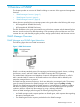
1 Overview of SNMP This chapter provides an overview of SNMP including an overview of the agent and management functions: • “SNMP Manager Overview” (page 5) • “SNMP Agent Overview” (page 6) • “SNMP Manager Functions” (page 8) Unless otherwise specified, the term storage system in this guide refers to the following disk arrays: • HP StorageWorks XP24000 Disk Array • HP StorageWorks XP20000 Disk Array The GUI illustrations in this guide were created using a Windows computer with the Internet Explore
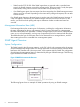
• SNMP uses the TCP/IP UDP. If the SNMP agent does not respond within a specified time period, the SNMP manager re-sends the request packet. That time period is set by the system administrator, taking into account the network traffic and operation policy. • If an SNMP agent again does not respond to the re-sent packet, the SNMP manager assumes that an error has occurred. Depending on the times set for polling and response, this can take several seconds.
Figure 3 Example of SNMP Operations SNMP Agent Functions SNMP Traps An SNMP agent reports a storage system error to a SNMP manager using the trap report function. If an error occurs, an SNMP agent issues an SNMP trap to an SNMP manager to report a failure. Issuing an SNMP trap, an SNMP agent also reports a product number, nickname, reference code, and an identifier of the component. The following table lists the events that trigger an SNMP agent trap.
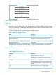
Error Report The following table lists the errors to be reported for the REQUEST operations. Table 3 SNMP Agent REQUEST Operations Error Description Corrective Action noError(0) Normal N/A noSuchName(2) • There are no MIB objects that are required. (Not supported). Verify that the requested object is correct. • The GETNEXT REQUEST command that is specified for the following object identifier of the last supported MIB object is received. readOnly(4) SET REQUEST is received.
Table 5 Storage system Component Status Types (continued) Status Description Moderate failure detected Partial failure. Service failure detected Minor failure.
2 Using the SNMP GUI This chapter explains the SNMP information tab: • “SNMP Information Tab” (page 10) SNMP Information Tab The SNMP IP Security tab allows you to limit SNMP access to specific SNMP managers and to enter SNMP trap addresses. Click Go – Install – SNMP SNMP IP Security in the menu bar of Remote Web Console Main window. The SNMP IP Security tab displays. Select the SNMP SNMP IP Security tab (see “SNMP Information Tab” (page 11)).
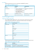
Figure 4 SNMP Information Tab Table 6 SNMP Information Tab Item Description Install The Extension SNMP check box is selected if the SNMP Agent feature is enabled. To set the SNMP Agent properties from XP Remote Web Console computer, select Extension SNMP on SNMP Information window. Manager The Manager section allows you to add and delete SNMP manager information (see “Adding SNMP Manager IP Addresses” (page 14)).
Table 6 SNMP Information Tab (continued) Item Description IP Address text box Enter the IP address of the manager that the SNMP Agent receives the request from. • Ipv4 and Ipv6 addresses can be specified for IP Address. However, if the OS of SVP is Windows XP and you enter Ipv6 address and select Apply, an error message is displayed and the Ipv6 address is not set. • Any IP address having all values set to zero (0) cannot be specified for Ipv4 and Ipv6.
Table 6 SNMP Information Tab (continued) Item Description System Group Allows you to add, delete or change SNMP system group information. If system group information has already been registered, the registered information displays. To register the system group information, the Extension SNMP check box must be selected. When you register system group information, select Apply. System group information is as follows: • Name: Connected storage system name.
3 Performing SNMP Operations This chapter covers adding and deleting an SNMP manager IP address, adding and deleting a community name, along with adding and deleting a community IP address: • “Adding SNMP Manager IP Addresses” (page 14) • “Deleting SNMP Manager IP Addresses” (page 15) • “Adding a Community Name” (page 16) • “Deleting a Community Name” (page 17) • “Changing a Community Name” (page 17) • “Adding Community IP Addresses” (page 18) • “Deleting a Community IP Address” (page 19) • “
6. Select Apply to implement the changes, or select Cancel to cancel the changes, then select OK on the confirmation message. Figure 5 Adding SNMP Manager IP Address (Top: Before Setting, Bottom: After Setting) Deleting SNMP Manager IP Addresses To delete an SNMP Manager IP address: 1. 2. 3. 4. 5. 6. Change to Modify mode. Log on to Remote Web Console. Click Go – Environmental Settings – SNMP Information in the menu bar of Remote Web Console Main window.
Figure 6 Delete IP Address Menu Adding a Community Name To add a community name: 1. 2. 3. 4. 5. 6. 7. 8. Change to Modify mode. Log on to Remote Web Console. Click Go – Environmental Settings – SNMP Information in the menu bar of Remote Web Console Main window. The SNMP Information window is displayed (see “SNMP Information Tab” (page 11)). In Community & Trap box, select and right-click Community. Add Community menu displays (see “Add Community Menu” (page 16)). Select Add Community.
Figure 8 Add Community dialog box Deleting a Community Name To delete a community name: 1. 2. 3. 4. 5. 6. Change to Modify mode. Log on to open Remote Web Console Main window, click Go – Environmental Settings – SNMP Information in the menu bar of Remote Web Console Main window. The SNMP Information window is displayed (see “SNMP Information Tab” (page 11)). In Community & Trap, select and then right-click the unwanted community. The Delete Community menu displays (see “Delete Community Menu” (page 17)).
4. 5. 6. 7. Select Change Community. The Change Community dialog box displays (see “Change Community dialog box” (page 18)). In the Community text box, overwrite the old community name with a new community name. You can use up to 180 alphanumeric characters, except for ", \, ;, :, ,, *, ?, <, >, |, /, ^, &, and %. You can also use spaces, except at the beginning or the end of the name. Select OK.
NOTE: 5. 6. • If the values for an IP address are all set to zero (0), that address cannot be specified for Ipv4 and Ipv6. • The Add IP Address dialog box does not support shortened expression for Ipv6 address. Enter 8 hexadecimal numbers that are separated colons (:) to a maximum 4 digits from zero (0) to FFFF inclusive. • When the OS of the SVP is Windows XP, if you enter an Ipv6 address and select Apply, an error message is displayed and the Ipv6 address cannot be set. Select OK.
5. 6. 7. Select Delete IP Address. A confirmation message displays. Select OK or Cancel. The selected IP address is deleted from Community & Trap, but the change is not yet implemented. Select Apply or Cancel. Select OK on the confirmation message. Figure 14 Delete Community IP Address Menu Testing the SNMP Trap Report To test the SNMP Trap report: 1. 2. 3. 4. 20 Log on to Remote Web Console. Click Go – Environmental Settings – SNMP Information in the menu bar of Remote Web Console Main window.
4 SNMP Supported MIB This chapter explains MIB specifications, standard and extension, the SNMP GUI, and trap configuration: • “Trap Configuration” (page 21) • “Standard MIB Specifications” (page 22) • “Extension MIB Specifications” (page 25) • “Extension MIB Configuration” (page 25) Trap Configuration Extension Trap Specifications The specifications of the supported extension trap are as follows.
Table 9 Failure Report Trap Name Object Identifier Type Description EventTrapSerialNumber 1.3.6.1.4.1.116.5.11.4.2.1 INTEGER The product number of the device that experienced the failure. EventTrapNickname 1.3.6.1.4.1.116.5.11.4.2.2 DisplayString The device nickname. EventTrapREFCODE 1.3.6.1.4.1.116.5.11.4.2.3 DisplayString The failure reference EventTrapPartsID 1.3.6.1.4.1.116.5.11.4.2.4 OBJECT IDENTIFIER The area where the failure occurred (Note). EventTrapDate 1.3.6.1.4.1.116.5.11.4.
Figure 15 Object System (1) Figure 16 Object System (2) Figure 17 Object System (3) Standard MIB Specifications 23
Supported Traps The following table shows the supported trap types. Table 11 Extension Trap Types Specific Trap Code Trap Description 1 RaidEventUserAcute All operations in a storage system stopped. 2 RaidEventUserSerious Operation in a component where a failure occurred stopped. 3 RaidEventUserModerate Partial failure. 4 RaidEventUserService Minor failure.
NOTE: The following symbols cannot be used: \ , / : ; * ? " < > | & % ^ Extension MIB Specifications Extension MIB Configuration “Extension MIB Configuration” (page 25) shows the Extension MIB configuration. Figure 18 Extension MIB Configuration raidExMibName raidExMibName indicates the SVP product name. raidExMibVersion raidExMibVersion indicates the microcode version.
raidExMibAgentVersion raidExMibAgentVersion indicates the internal version of the extension MIB. Number of Storage Systems under Control of SVP (raidExMibDkcCount) raidExMibDkcCount suggests the number of a storage system under the control of SVP. raidExMibRaidList raidExMibRaidList indicates the storage system under the control of the SVP.
The following table shows the type of information displayed for each storage system Table 13 Storage system Information Name Type Description Mounted Value Attribute raidlistSerialNumber INTEGER Storage system product number (index). 1-99,999 read-only DisplayString Storage system nickname. (Max. 18 characters) read-only DisplayString Microcode version. (Max. 10 characters) read-only DisplayString Storage system product type.
The following table describes the status of the storage system components Table 14 Storage system component information Name Type Description MIB Value Attribute DKCRaidListIndexSerialNumber INTEGER Storage system product number (index). 1-99,999 read-only INTEGER Status of processor. Note read-only ::=dkcHWEntry(1) DKCHWProcessor ::=dkcHWEntry(2) DKCHWCSW (1 digit) INTEGER Status of internal star. ::=dkcHWEntry(3) DKCHWCache INTEGER Status of cache.
dkuHWEntry dkuHWEntry indicates the status of the disk unit components. Table 15 Storage System component information Name Type Description MIB Value Attribute DKURaidListIndexSerialNumber INTEGER Storage system product number (index). 1-99,999 read-only INTEGER Status of power supply. Note read-only ::=dkuHWEntry(1) DKUHWPS ::=dkuHWEntry(2) DKUHWFan (1 digit) INTEGER Status of fan.
NOTE: The status of each component is indicated as follows: 1: Normal. 2: Acute failure detected. 3: Serious failure detected. 4: Moderate failure detected. 5: Service failure detected. raidExMibDKCHW2 raidExMibDKCHW2 indicates the status of the storage system components. Table 16 Storage system components information 2 Name Type Description MIB Value Attribute DKC2RaidListIndexSerialNumber INTEGER Storage system product number (index).
NOTE: The status of each component is indicated as follows: 1: Normal. 2: Acute failure detected. 3: Serious failure detected. 4: Moderate failure detected. 5: Service failure detected. raidExMibTrapList raidExMibTrapList suggests the history of the failure traps. Table 17 Failure Information Name Type Description MIB Value Attribute EventListIndexSerialNumber INTEGER Storage system product number (index). 1-99,999 read-only DisplayString Storage system nickname. (Max.
Table 17 Failure Information (continued) Name Type Description MIB Value Attribute EventListTime DisplayString Time when the failure occurred. hh:mm:ss read-only Detailed information about the failure.
Figure 20 Extension MIB Configuration (2) Extension MIB Configuration 33
5 SNMP Failure Trap Reference This chapter shows the alert level, the trap reference code, the description, and the alert level: • “SNMP Failure Trap Reference Codes” (page 34) • “SIM List for TrueCopy for Mainframe Errors” (page 40) The following table shows the alert level, the trap reference code, the description, and the alert level.
Table 18 SNMP Failure Trap Reference Codes (continued) Trap Reference Code Description Alert Level SIM22 SIM23 SIM13 FF C2 xy Cache Module Blockade processing finished FF C3 0x Cache Package Blockade processing finished SERVICE FF F1 xy Cache temporary failure SERVICE FF F2 xy Module blockade MODERATE FF F3 0x Package blockade MODERATE FF F4 0x Module group blocking SERIOUS FF E2 0x Area blocking SERIOUS FF E9 01 HP StorageWorks XP for Compatible Parallel Access Vo
Table 18 SNMP Failure Trap Reference Codes (continued) Trap Reference Code 36 Description Alert Level SIM22 SIM23 SIM13 46 2y xx Dynamic sparing normal end SERVICE 46 3y xx Dynamic sparing abnormal end MODERATE 46 5y xx Dynamic sparing warning end SERVICE 49 0x xx Sidefile 40% over SERVICE AC 50 xy HDU power supply shutdown detected Power supply (DKU) MODERATE BF 0x A5 Fuse failure Environmental failure MODERATE BF 0x A6 Fuse failure MODERATE BF 1x 1x Abnormal
Table 18 SNMP Failure Trap Reference Codes (continued) Trap Reference Code Description Alert Level SERIOUS SIM22 SIM23 SIM13 7F F6 0x Virus detected (Virus isolation failed) 7F F7 xx Expiration 7F F8 xx Exceeded the licensed capacity SERIOUS 7F F9 xx Program product invalidated by the expiration of the prerequisite program product. SERIOUS 7F FF FF This is not a failure but a test code. This code is output only by the SNMP trap.
Table 18 SNMP Failure Trap Reference Codes (continued) Trap Reference Code SIM22 SIM23 SIM13 DB 3x yy Description Alert Level A currently used M-VOL has been suspended because DFW to R-VOL was prohibited. SERIOUS x: The CU number yy: The LDEV number DB 4x yy A currently used M-VOL has been suspended because an operation for suspending an R-VOL was performed.
Table 18 SNMP Failure Trap Reference Codes (continued) Trap Reference Code Description Alert Level SIM22 SIM23 SIM13 DC 4x xx Volume used as P-VOL has been suspended (S-VOL suspension detected) SERIOUS DC 5x xx Volume used as P-VOL has been suspended (S-VOL pair deletion detected) SERIOUS DC 6x xx Volume used as S-VOL has been suspended (Unable to restore path) SERIOUS DC 7x xx Volume used as S-VOL has been suspended (RCU failure detected) SERIOUS DC 9x yy Volume used as a P-VOL
Table 18 SNMP Failure Trap Reference Codes (continued) Trap Reference Code Description Alert Level SIM22 SIM23 SIM13 62 2x xx Pool became full. MODERATE 62 3x xx Pool detected a failure. MODERATE 62 40 00 No free area in SM. MODERATE 62 50 00 The pool usage threshold is being exceeded. MODERATE 63 0x xx Exceeded the XP Thin Provisioning volume usage threshold. MODERATE The SIM Code for TrueCopy for Mainframe errors is determined by the mode.
6 Troubleshooting This chapter provides troubleshooting information for the HP StorageWorks XP24000/XP20000 SNMP Agent Reference Guide: • “Mitigating SNMP Errors” (page 41) • “Calling HP Technical Support” (page 41) Mitigating SNMP Errors Use setup.exe when you install a secondary SVP. If you do not, traps could be reported to an IP address that is not specified in SNMP settings.
7 Support and Other Resources Related Documentation • HP StorageWorks XP24000/XP20000 LUN Manager User Guide • HP StorageWorks XP24000/XP20000 Disk Array Owner Guide • HP StorageWorks XP24000/XP20000 Remote Web Console User Guide • HP StorageWorks XP10000 Disk Array Owner Guide • HP StorageWorks XP12000 Disk Array Owner Guide • HP StorageWorks XP12000/XP10000 Remote Web Console User Guide You can find these documents on the HP Manuals website: http://www.hp.
• Operating system type and revision level • Detailed questions Subscription Service HP recommends that you register your product at the Subscriber’s Choice for Business website: http://www.hp.com/go/e-updates After registering, you will receive email notification of product enhancements, new driver versions, firmware updates, and other product resources. HP Websites For additional information, see the following HP websites: • http://www.hp.com • http://www.hp.com/go/storage • http://www.hp.
Glossary A ADP ADaPter. Hardware that connects the LCM to the CHA physically and logically. C CAC Common access card. CHA Channel adapter. CU Control unit. D DASD Direct-access storage device. DFW DASD fast write. DKC Disk controller. DKU Disk unit. DRV Driver. F FCA Fibre Channel adapter. FD Floppy disk. H HDD Hard disk drive. HTP Hyper Transfer Program. L LCM Link Control Module. LD, LDEV Logical device.
RIO Remote I/O. S SGMP Simple Gateway Management Protocol. SIM Service information message. SM Shared memory. SVP Service processor. A computer built into a disk array. The SVP, used only by an HP service representative, provides a direct interface to the disk array. U UDP User Datagram Protocol. V VOL, vol Volume.
Index A adding SNMP community IP address, 18 SNMP community name, 16 SNMP managers, 14 C changing SNMP community name, 17 conventions storage capacity values, 42 D deleting SNMP community IP address, 19 SNMP community name, 17 SNMP managers, 15 document related documentation, 42 documentation HP website, 42 providing feedback, 43 H help obtaining, 42 HP technical support, 42 I instructions adding SNMP community IP address, 18 adding SNMP community name, 16 adding SNMP managers, 14 changing SNMP communit