HP StorageWorks XP24000/XP20000 Disk Array Site Preparation Guide Part Number: AE002-96055 Seventh edition: October 2010
Legal and notice information © Copyright 2008, 2010 Hewlett-Packard Development Company, L.P. Confidential computer software. Valid license from HP required for possession, use or copying. Consistent with FAR 12.211 and 12.212, Commercial Computer Software, Computer Software Documentation, and Technical Data for Commercial Items are licensed to the U.S. Government under vendor's standard commercial license. The information contained herein is subject to change without notice.
Contents 1 Site preparation team and tasks ........................................................... 9 Site preparation team .................................................................................................................. 9 HP representative responsibilities ............................................................................................ 9 Customer responsibilities .......................................................................................................
Preventing metallic particulate contamination ......................................................................... Data communication requirements ............................................................................................... HP StorageWorks XP Continuous Track (C-Track) ..................................................................... HP Insight Remote Support Advanced ................................................................................... Electrical requirements .....
Rack stability ............................................................................................................................ Subscription service .................................................................................................................. HP websites ............................................................................................................................. Documentation feedback ...........................................................................
Figures 1 Delivery form .......................................................................................................... 23 2 Single rack recommended floor cutouts – option 1 ...................................................... 28 3 Single rack recommended floor cutouts – option 2 ...................................................... 29 4 Expansion (dual) rack recommended floor cutouts – option 1 ........................................
Tables 1 XP24000 dimensions .............................................................................................. 14 2 XP20000 dimensions .............................................................................................. 14 3 XP24000 DKC and DKU min/max configuration weights ............................................. 15 4 XP20000 maximum configuration weights ................................................................. 15 5 Component heat, power, and weight specifications ......
1 Site preparation team and tasks The objective of site preparation is to prepare your site for the successful and timely installation of this HP product. Proper site preparation is vital for the reliability of the disk array. Site preparation involves a careful balance of equipment design criteria, site environmental variables, your business needs, and your budget constraints. In addition to this guide, other resources may be available to you.
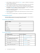
3. Use the information, instructions, and tools in Chapter 2, page 13 to determine site requirements for specific disk array components. 4. In the site preparation checklist, answer each item Yes or No as it relates to your site. The checklist refers to the pages in this guide where you can find more information about each item. 5. If you answer No to any item, your site may not meet site requirements for the disk array.
* Checklist questions Yes No Reference * Does the new floor plan include the clearance required for the floor's load rating? XP24000 and XP20000 floor clearance requirements, page 27 * Is the computer room structurally complete (walls, floor, air conditioning system, and so on)? Computer room requirements, page 23 * Is the floor adequate for the equipment load? XP24000 and XP20000 floor clearance requirements, page 27 Is antistatic flooring or mats installed? Floor covering requirements, page
* Checklist questions Yes No Reference * Have all sources of electrical interferences been corrected? Sources of electrical interference, page 43 Does the customer site have access control (for example, will HP representatives need an escort)? NA Does the computer room have access control (for example, will HP representatives need a security code)? NA * Are all floors, stairs, elevators, stairwalkers, lifts, ramps, or ladders needed to move the equipment adequate to support its weight and size?
2 Site requirements for the HP Disk Arrays Your site must meet the following requirements before HP can deliver and install the system. This chapter describes these requirements in detail: • • • • • • • Delivery area requirements.
TIP: XP components are installed without sliding rails in the XP20000 rack assembly, so the rack does not require stabilizers. If you install other equipment in the rack, you must consider adding stabilizers. For information about stabilizers, ballasts, tie-down option kits and other options for the HP 10000 model 10642 G2 rack, see the rack options website: http://www.hp.
U height 106.68 42 Weights Use the approximate packaged weights when determining delivery requirements, and unpackaged weights to calculate the total weight of your configuration. Plan your facility to accommodate the weight of the maximum configuration for each disk array even if you expect to start with an empty rack and add components later. For weights of individual components, see Table 5 on page 15. Table 3 XP24000 DKC and DKU min/max configuration weights Frame configuration kg (min/max config.
Product Number Description Heat Output (kW) Power (kVA) Weight (kg/lbs) #002 3P/30A/50Hz No Plugs 2 Cords — — 7.10/15.65 #003 1P/50A/60Hz 9P53U2 2 Cords — — 8.70/19.18 #004 1P/50A/50Hz No Plugs 2 Cords — — 6.80/14.99 #005 1P/30A/60Hz 3750DP 4 Cords — — 9.00/19.84 #006 1P/30A/50Hz No Plugs 4 Cords — — 7.10/15.65 AE132A HP XP24000 SVP High Reliability Kit 0.079 0.081 4.17/9.19 AE133A HP XP24000 Power Control I/F MF Kit 0.002 0.002 0.30/0.
Product Number Description Heat Output (kW) Power (kVA) Weight (kg/lbs) AE187A HP XP24000 Cache Backup Expansion Kit 0.010 0.010 0.12/0.26 AE188A HP XP24000 Cache Backup DKC/DKU Cable 0.001 0.010 0.12/0.26 AE155A HP XP24000 Shared Memory Adapter 0.005 0.005 1.20/2.65 AE156A HP XP24000 2-GB Shared Memory 0.013 0.013 0.08/0.18 AE157A HP XP24000 4-GB Shared Memory 0.013 0.013 0.08/0.18 AE160A HP XP24000 DKC 12V Battery 0.029 0.030 14.00/30.
Product Number Description Heat Output (kW) Power (kVA) Weight (kg/lbs) #004 1P/50A/50Hz No Plugs 2 Cords — — 6.80/14.99 #005 1P/30A/60Hz 3750DP 4 Cords n/a n/a 9.00/19.84 #006 1P/30A/50Hz No Plugs 4 Cords n/a n/a 7.10/15.65 AE174A HP XP24000 DKU Disk Expansion Kit 0.291 0.300 37.70/83.11 AE176A HP XP24000 73 GB 15k rpm Array Group 0.080 0.084 3.60/7.94 AE215A HP XP20000 Enhanced DKA Disk Adapter Pair 0.099 0.102 2.60/5.73 AE176AS HP XP24000 73GB 15k rpm Spare Disk 0.
Product Number Description Heat Output (kW) Power (kVA) Weight (kg/lbs) AE183A HP XP24000 450GB 15K rpm HDD Array Group 0.080 0.084 3.60/7.94 AE183AS HP XP24000 450GB 15K rpm Spare Disk 0.020 0.021 0.90/7.94 AE184A HP XP24000 73GB SSD Array Group 0.040 0.044 2.00/4.41 AE184AS HP XP24000 73GB SSD Spare Disk 0.010 0.011 0.50/1.10 AE185A HP XP24000 146GB SSD Array Group 0.040 0.044 2.00/4.41 AE185AS HP XP24000 146GB SSD Spare Disk 0.010 0.011 0.50/1.
Product Number Description Heat Output (kW) Power (kVA) Weight (kg/lbs) AE200A HP XP20000 73-GB 15krpm Array Group 0.080 0.084 3.60/7.94 AE200AS HP XP20000 73GB 15k rpm Spare Disk 0.020 0.021 0.90/1.98 AE201A HP XP20000 146-GB 15k-rpm Array Group 0.080 0.084 3.60/7.94 AE201AS HP XP20000 146GB 15k rpm Spare Disk 0.020 0.021 0.90/1.98 AE202A HP XP20000 300-GB 10k-rpm Array Group 0.080 0.084 3.60/7.94 AE202AS HP XP20000 300GB 10k rpm Spare Disk 0.020 0.021 0.90/1.
Product Number Description Heat Output (kW) Power (kVA) Weight (kg/lbs) AE209AS HP XP20000 146GB SSD Spare Disk 0.010 0.011 0.50/1.10 AE210A HP XP20000 200GB SSD Spare Disk 0.040 0.044 2.00/4.41 AE210AS HP XP20000 200GB SSD Spare Disk 0.010 0.011 0.50/1.10 AE211A HP XP20000 400GB SSD Array Group 0.040 0.044 2.00/4.41 AE211AS HP XP20000 400GB SSD Array Group 0.010 0.011 0.50/1.10 AE212A HP XP20000 600GB 15K FC HDD Array Group 0.080 0.084 3.60/7.
CAUTION: Make sure that your doorways and hallways provide enough clearance to move the equipment safely from the delivery area to the computer room. Permanent obstructions such as pillars or narrow doorways can cause equipment damage. If necessary, plan for the removal of walls or doors. CAUTION: Make sure all floors, stairs, and elevators used when moving the disk array to the computer room can support the weight and size of the equipment. Failure to do so could damage the equipment or your site.
Figure 1 Delivery form . Restricted access HP does not recommend tipping loaded racks to navigate stairs or height restricted doorways. If you have restricted access contact your HP service representative. Your HP service representative will contact the HP Storage Technology Center. Computer room requirements The goal of a computer room is to maintain an ideal environment for computer equipment, including this system.
Preventing electrostatic discharge Electrostatic discharge (ESD) can cause component damage, especially during servicing operations. Static charges occur when objects are separated or rubbed together. The voltage level of a static charge is determined by the following factors: • Types of materials • Relative humidity — low humidity increases ESD voltage • Rate of change — a standard air conditioner cools the air and lowers humidity. The faster the air is cooled and dried, the greater the likelihood of ESD.
Consult your insurance carrier and local fire department for fire safety suggestions. They can analyze your existing fire control systems and advise you about any required changes. If you are building a new site or making structural changes to an existing site, consult your local building codes for fire prevention and protection guidelines. Avoiding equipment servicing hazards Your staff and HP service personnel require safe access to the system.
WARNING! If metal is used in the construction of the computer room floor, ensure that there is a common ground connection between it and the ground or floor that it is built on to avoid possible build up of different voltage potentials. Noncompliance can result in serious injury to personnel and damage to equipment.
CAUTION: HP strongly discourages carpeting within 6.0 m (20 ft.) of the disk array. Carpeting may shed dust that can cause problems with the disk array. CAUTION: If your computer room has carpeting, place static discharge mats so that personnel must walk across them before touching any part of the array. Failure to comply with this precaution can result in equipment damage through static discharge.
Figure 2 Single rack recommended floor cutouts – option 1 . Item Description A 9.00 in. (230 mm) B 2.25 in. (57mm) C 6.00 in. (150 mm) Allowable tolerance: +/– 0.125 in (+/– 3.
Figure 3 Single rack recommended floor cutouts – option 2 . Item Description A 4.500 in. (230 mm) B 2.25 in. (57mm) C 6.00 in. (150 mm) Allowable tolerance: +/– 0.125 in (+/– 3.
Figure 4 Expansion (dual) rack recommended floor cutouts – option 1 . Item Description A 9.00 in. (230 mm) B 2.25 in. (57mm) C 6.00 in. (150 mm) Allowable tolerance: +/– 0.125 in (+/– 3.
Figure 5 Expansion (dual) rack recommended floor cutouts – option 2 . Item Description A 4.50 in. (115 mm) B 2.50 in. (57 mm) C 6.00 in. (150 mm) Allowable tolerance: +/– 0.125 in (+/– 3.2 mm) XP24000 cutouts The figures in this section show the locations of floor cutouts under the XP24000 DKC and XP24000 DKU for electrical cables. Position floor cutouts toward the center of the cabinet.
Figure 6 DKC . Figure 7 DKU .
Environmental requirements The environmental specifications for operating this system must be satisfied before installation. Altitude requirements The maximum altitude for system operation is 3,000 meters (9,842 feet). The minimum altitude for system operation is –60 meters (–197 feet). Air conditioning requirements Use separate computer room air conditioning duct work. If it is not separate from the rest of the building, it might be difficult to control cooling and air pressure levels.
Humidity specifications Maintain the humidity levels specified in Table 7. High humidity levels cause galvanic actions to occur between some dissimilar metals. This eventually causes a high resistance between connections, leading to equipment failure. Low humidity contributes to undesirably high levels of electrostatic charge. This increases the electrostatic discharge (ESD) voltage potential. ESD can cause component damage during servicing operations.
Condition Specification Shipping and storage 0.5 G, 15 min. (at four most severe resonances between 5 and 200 Hz) (product packed in factory packing) Shock specifications Table 9 lists shock specifications. For horizontal shock testing methods, see ASTM D5277-92 Standard Test Methods for Performing Programmed Horizontal Impacts Using an Inclined Impact Tester.
DKC Each DKU Full array (1 DKC and 4 DKUs) 21997 21406 107623 5543 5394 27120 Parameter Max. BTUs per hour Max. kcal per hour Table 11 XP20000 maximum heat and power specifications Parameter Primary Rack Second Rack Full array Power consumption (kVA) 4.2 3.0 7.2 Heat dissipation (kW) 4.0 2.9 6.9 BTUs per hour 13702 9788 23490 Kcal per hour 3453 2467 5919 Table 12 shows the disk array's air flow requirements.
Preventing metallic particulate contamination Metallic particulates can be especially harmful around electronic equipment. This type of contamination may enter the data center environment from a variety of sources, including but not limited to floor tiles, worn air conditioning parts, heating ducts, rotor brushes in vacuum cleaners, or printer component wear. Because metallic particulates conduct electricity, they have an increased potential for creating short circuits in electronic equipment.
Item Purpose A public voice phone line near the disk array Needed to allow your staff and HP representatives to communicate inside and outside your site. HP StorageWorks XP Continuous Track (C-Track) The HP StorageWorks XP Continuous Track (C-Track) remote support solution detects and reports events to the XP Remote Monitoring Center (RMC). C-Track transmits heartbeats, system information messages (SIMs), and configuration information for remote data collection and monitoring purposes.
HP Product AE242A AE243A AE244A AE245A Description Application HP XP No Remote Device Access w/LAN Supp (Default) For customers that commit to utilize Internet and Insight Remote Support connectivity for XP Remote Device Monitoring but will not allow for Remote Device Access to the XP array from HP for proactive and critical support processes. With no Remote Device Access, Critical Support contract prerequisites cannot be met.
Avoid the use of a line voltage conditioner. Make sure that a power distribution unit (if used) provides the correct voltage to support your entire system. Frequency Usually, AC line frequency is determined by your local power providers. In some cases, electrical power is supplied by generators. Shifts in AC line frequency can cause system errors. An HP representative can monitor the frequency of the input AC line power and make recommendations, if necessary.
Fault-tolerant AC power examples Figure 8 Fault-tolerant AC wiring diagram . When receptacles are used to connect disk array components to AC power, they must include a dedicated ground connection that is insulated from the receptacle. It is important that the receptacle box be grounded with an additional ground connection that is separate from the dedicated ground. The additional ground can be hard conduit.
If necessary, an HP representative can measure your power line noise level and make appropriate recommendations concerning the use of line treatment devices. Protection against sources of electrical interference Table 15 describes ways to protect the disk array from electrical interference.
Sources of electrical interference Ensure that the disk array is protected from sources of electrical interference. Table 16 Sources of electrical interference Potential source Description Wall outlets Convenience power outlets for building maintenance equipment (such as vacuum cleaners and floor buffers) must be wired from circuit breakers on a power panel separate from the computer system panel.
Site requirements for the HP Disk Arrays
3 Electrical specifications for the HP Disk Arrays The detailed electrical specifications in this chapter can help the site electrician perform any necessary electrical preparation. The sections are specific to each disk array. Review the appropriate section for your product. XP24000 electrical specifications XP24000 AC line voltage requirements The following are the AC line voltage requirements for each HP disk array. The following tables present power specifications.
Parameter 200 VAC 50 or 60 Hz Number of circuit breakers 208 VAC 60 Hz only 2 220 VAC 50 Hz only 2 230 VAC 50 or 60 Hz 240 VAC 50 Hz only 2 2 2 Table 18 DKC power specifications, 30-amp, 50 or 60 Hz, single-phase Parameter 200 VAC 50 or 60 Hz 208 VAC 60 Hz only 220 VAC 50 Hz only 230 VAC 50 or 60 Hz 240 VAC 50 Hz only Minimum operating 184 191 202 212 221 212 220 233 244 254 9.10 8.77 8.29 7.9 7.
Parameter Number of power cords 200 VAC 50 or 60 Hz 208 VAC 60 Hz only 220 VAC 50 Hz only 230 VAC 50 or 60 Hz 240 VAC 50 Hz only 380 VAC 50 Hz only 400 VAC 50 Hz only 415 VAC 50 Hz only 2 2 2 2 2 2 2 2 Recommended circuit breakers (amps) 30 30 30 30 30 30 30 30 Number of circuit breakers 2 2 2 2 2 2 2 2 Table 20 DKU power specifications, 50-amp, 50 or 60 Hz, single-phase Parameter 200 VAC 50 or 60 Hz 208 VAC 60 Hz only 220 VAC 50 Hz only 230 VAC 50 or 60 Hz 240 VAC 5
Parameter 200 VAC 50 or 60 Hz 208 VAC 60 Hz only 220 VAC 50 Hz only 230 VAC 50 or 60 Hz 240 VAC 50 Hz only Maximum operating 212 220 233 244 254 8.91 8.59 8.12 7.74 7.
XP24000 receptacle part numbers and ordering information Table 23 lists the plug and receptacle part numbers for 60-Hz configurations of the HP XP24000 disk array. Table 23 XP24000 receptacle part numbers Power source Breaker rating Plug Receptacle 30 A Russellstoll or Thomas & Betts 3750DP Russellstoll or Thomas & Betts 3933 (alt. 9C33U0) or 3753 (alt.
Figure 9 30-amp, three-phase power cords . If one power source malfunctions, the other power source assumes the total load, providing uninterrupted operation. HP recommends that each power cord have a separate electrical circuit as its source, in case of a circuit failure. Each power supply cord is supplied with an attachment plug type DDK 115J-AP8508. TIP: DDK115J-AP8508 plug has the same fit and form as the Russellstoll (T&B) 3760PDG plug and is fully compatible with Russellstoll (T&B) connectors.
CAUTION: An HP representative should be present whenever the disk array is being connected to a new power source for the first time. Connecting the power supply cords (Europe) All 50-Hz, European HP XP24000 disk array racks are shipped with unterminated power cords. Your electrician must select and install the correct power plug. Be sure to prepare the socket receptacles and power cords between the power distribution board of the building and the attachment plugs for the unit.
XP24000 single-phase AC cabling for the USA When configured for 50-amp, single-phase power, each XP24000 disk array rack has two power cords and two main disconnect devices so that AC power can be supplied from separate power distribution panels. When configured for 30-amp, single-phase power, each HP XP24000 disk array rack has four power cords and four main disconnect devices.
Figure 12 Connecting 30-amp, single-phase power cords . Be sure to install Russellstoll 3933 (alternate, 9C33U0) or 3753 (alternate, 9R33U0W) socket receptacles between the power distribution panel of the building and the power plugs for the unit. The power cords provided with the disk array are nonshielded, type ST or equivalent with three #10 AWG (minimum) conductors terminated at one end with an assembled plug connector.
Connecting the power supply cords (Europe) 50-amp single phase power cords for Europe Each 50-amp HP XP24000 disk array rack has two power supply cords. The power cords included with the unit are type H07RN-F or equivalent with three 10 square mm conductors. CAUTION: Be sure to connect the power cords to the distribution panel as shown in the following figure. Improper wiring of the neutral conductor may cause damage to the disk array.
an HP XP24000 disk array with the 30-amp power option to comply with these local codes. Your electrician knows the appropriate code requirements for your location/site. XP20000 electrical specifications XP20000 AC line voltage requirements The AC power requirements, shown in Table 24, are essentially the same for primary and secondary racks. Each rack operates on 200 VAC nominal, 20 amps, 50 or 60 Hz, single-phase power.
shown in Figure 14 and Figure 15. This provides fault-tolerant operation of the disk array. Each pair of AC inputs must be capable of supporting the entire current demand for the rack. Each PDU is fitted with an IEC320-C20 inlet that fits the supplied input power cord. CAUTION: The four PDU outputs shown in the following figures are for internal power connections to the disk array only. Do not connect any other equipment to these outlets.
Figure 15 Power cabling in a primary rack with a disk controller and one or two disk chassis . The second rack shown in Figure 16 has four connections to AC power. Its power requirements are 200 VAC, single phase, 20 amps.
Figure 16 Power cabling in a secondary rack with one or two disk chassis . North American AC power cabling Each XP20000 rack requires 20-amp, single-phase 200 VAC power supplied by four power cords with plugs, four receptacles, and four main disconnect devices (circuit breakers). If the second rack contains only one disk chassis, only two power cords and breakers are required, but four are required if you plan to add another disk chassis.
European AC power cabling Each XP20000 rack requires 20-amp, single-phase 200 VAC power supplied by four power cords with plugs, four receptacles, and four main disconnect devices (circuit breakers). If the second rack contains only one disk chassis, only two power cords and breakers are required, but four are recommended if you plan to add another disk chassis later. The XP20000 disk array comes from the factory with the AC power cables and plugs or stripped ends based on the power option ordered.
WARNING! High leakage current can occur between the power supply and the unit. To avoid electrical shock, be sure to make the protective earth connection before the supply connections.
4 Delivery and unpacking The disk array equipment is shipped directly from HP. If the disk array is part of a system order, HP coordinates shipment from all HP locations so that all of the equipment arrives at the site at approximately the same time. When your equipment is shipped, HP provides you with carrier information and an expected delivery date. Factors beyond HP's control can cause delivery delays.
Required tools • Claw hammer (if full packaging with wooden crate) • Open-end or socket wrench 11mm (7/16 in) , 12mm (8/16 in), 14mm (9/16 in), and 17mm (11/16 in), or adjustable wrench • Scissors or box knife to cut polyester banding • Safety glasses • Short stepladder (helpful, but not required) Packaging configurations XP disk array racks are shipped in one of three standard packaging configurations: • Environmental pack (XP24000 only)— consists of stretch wrap over corner protectors.
WARNING! When using sharp objects or cutting tools, make sure that no part of your body lies in the path of the blade bit or point. CAUTION: When disk array equipment is not located in a data center or computer room, it must be stored in a controlled area that meets environmental requirements. CAUTION: For the XP24000, when detached from each other, DKCs and DKUs do not have side panels.
1. If shipped in a wooden crate: a. Using an 11 mm (7/16 inch) ratchet or wrench, remove the six lag screws at the base of the crate. b. Using the claw end of a claw hammer, remove the crate clamps, and then remove the crate panels. WARNING! Crate clamps are under tension. Wear safety glasses and hold onto the clamp with your free hand during removal. Steps 2 through 5 refer to Figure 18. 1. Polyester bands 3. Carton fasteners Figure 18 Removing the outer carton . 64 Delivery and unpacking 2.
2. Cut and remove the polyester bands. 3. Remove the nails attaching the carton to the pallet. 4. Remove the plastic carton fasteners. 5. Remove the carton. Steps 6 through 8 refer to Figure 19. 4. Accessory boxes 5. Ramp 6. Corner pads 7. Pallet adapter plates 8. Poly bag Figure 19 Unpacking the disk array . 6. Remove the accessory boxes, ramp, and corner pads. 7. Using a 6 mm hex and 19 mm wrench, remove the adapter plates that anchor the rack to the pallet. 8.
10. Visually check the unit for any damage. If any damage is visible, report it immediately to HP and the shipping carrier. Moving racks Use care when moving racks with casters. • Sudden stops, excessive force, and uneven surfaces may cause the product to overturn. • The XP rack has casters which are fixed in the front and swivel in the rear for stability and safety.
5 Support and other resources Related documentation The following documents provide related information: • HP StorageWorks XP24000/XP20000 Disk Array Owner Guide • HP StorageWorks XP24000/XP20000 Remote Web Console User Guide • HP StorageWorks XP disk array configuration guides for specific operating systems You can find these documents on the HP Manuals website: http://www.hp.com/support/manuals In the Storage section, click Disk Storage Systems and then select a product.
WARNING! To reduce the risk of personal injury or damage to equipment: • Extend leveling jacks to the floor. • Ensure that the full weight of the rack rests on the leveling jacks. • In multiple-rack installations, fasten racks together securely. Subscription service HP recommends that you register your product at the Subscriber's Choice for Business website: http://www.hp.
Glossary AL Arbitrated loop. allocation The ratio of allocated storage capacity versus total capacity as a percentage. Allocated storage refers to those logical devices (LDEVs) that have paths assigned to them. Allocated storage capacity is the sum of the storage of these LDEVs. Total capacity is the sum of the capacity of all LDEVs on the disk array. AL-PA Arbitrated loop physical address.
are numbered sequentially. The disk array supports a certain number of CUs, depending on the disk array model. Each CU can manage multiple LDEVs. Therefore, to uniquely identify a particular LDEV requires both the CU number and the LDEV number. CS Critical Support. CSR Customer self repair. CU Control unit. CVS Custom volume size. CVS devices (OPEN-x CVS) are custom volumes configured using array management software to be smaller than normal fixed-size OPEN system volumes.
failover Disconnecting a failed unit or path and replacing it with an alternative unit or path in order to continue functioning. FAN Factory Authorization. FC Fibre Channel. A network technology primarily used for storage networks. FC-AL Fibre Channel arbitrated loop. FCP Fibre Channel Protocol. fence level A method of setting rejection of P9000 or XP Continuous Access write I/O requests from the host according to the condition of mirroring consistency. FICON Fibre connectivity.
mirroring consistency The consistency (usability) of data in a volume (for example, S-VOL). MR Magnetoresistive. mutual hot standby system Two servers that are poised to cover for each other if necessary. NAS Network attached storage. node An environment where instances can be executed, logically speaking. Physically, a processor, which is an element of a cluster system. NVS Nonvolatile storage. OFC Open Fibre Control. OLM Optical link module. OS Operating system. PA Physical address.
R/W, r/w Read/write. RAID group One or two array groups formatted with a common RAID level. RAID1 parity groups consist of 4 HDDs (2D+2D) or 8 HDDs (4D+4D). RAID5 parity groups include a parity disk but also consist of 4 HDDs (3D+1P) or 8 HDDs (7D+1P). All RAID6 array groups are made up of 8 HDDs (6D+2P). RAID level A RAID Level is one of the ways that disk drives are grouped together to improve performance, data availability/reliability or both. RAID levels are defined from RAID0 to RAID6.
VSC 74 Volume size customization. Also known as CVS.
Index A AC plugs, 55 power, 55 AC cabling European, 59 AC cabling North American, 58 AC line voltage, 45 acoustics, 35 air pressure, 23 air conditioning, 33 and metallic particulate contamination, 37 altitude, 33 antistatic carpeting, 27 containers, 24 B branch circuit requirements, 51, 53, 54, 58, 59 breakers, 55 building codes, 23, 25, 40 C C-Track, 37, 38, 67 cables, 25, 55 and mechanical vibration, 35 and raised floors, 26 as safety hazards, 25 Cat 5, 37 in floor plans, 25 power, 55 routing, 37 sealin
environmental requirements, 33, 37 equipment servicing hazards, 25 ESD, 24, 34 European AC power cabling, 59 F fire safety, 24 floor, 25 clearances, 27 conductive, 24 covering, 26 cutouts, 25 grid panels, 26 grounding, 24, 26 load rating, 26 tiles, and metallic particulate contamination, 37 waxed, 24 floor plan, 25 frequency, 40 humidity, 34 and ESD, 24 I Internet-based remote support, 37, 38, 67 Internet-based remote support, 37, 38, 67 L LAN connection, 37 lightning, 42, 43 line current, 55 M metalli
power requirements, 39, 45 uninterruptible, 42 AC connections, 55 cables, 55 consumption, 35 cords, 45, 46, 47, 48, 55 cords, floor cutouts for XP20000, 27 cords, floor cutouts for XP24000, 31 cords, single-phase for Europe, 54 cords, three-phase for Europe, 51 cords, single-phase for Europe, 54 cords, single-phase for USA, 52, 53 cords, three-phase for Europe, 51 cords, three-phase for USA, 49, 50 line transients, 41 power cabling North American, 58 power cabling European, 59 space planning, 25 specificat