HP StorageWorks XP24000/XP20000 Disk Array Owner Guide Abstract This guide describes the operation of the HP StorageWorks XP24000/XP20000 Disk Arrays. Topics include a description of the disk array hardware, instructions on how to manage the disk array, descriptions of the disk array control panel and LED indicators, troubleshooting, and regulatory statements.
Legal and notice information © Copyright 2008, 2010 Hewlett-Packard Development Company, L.P. Confidential computer software. Valid license from HP required for possession, use or copying. Consistent with FAR 12.211 and 12.212, Commercial Computer Software, Computer Software Documentation, and Technical Data for Commercial Items are licensed to the U.S. Government under vendor's standard commercial license. The information contained herein is subject to change without notice.
Contents 1 Overview of the HP XP24000/XP20000 Disk Array ............................... 7 Outstanding performance, capacity, and reliability ......................................................................... 7 Continuous data availability ......................................................................................................... 7 Nondisruptive service and upgrades ............................................................................................. 8 Connectivity .............
Powering down the disk array .................................................................................................... Planned power off .............................................................................................................. Emergency power off .......................................................................................................... To power off the disk array in an emergency ...................................................................
Figures 1 Disk array simplified SAN connection .......................................................................... 9 2 XP24000 system architecture .................................................................................... 20 3 XP20000 system architecture .................................................................................... 21 4 Disk array frames ....................................................................................................
Tables 1 Remote Web Console-based software for XP24000/XP20000 disk arrays ..................... 12 2 Host/Server-based software for the XP24000/XP20000 disk arrays .............................. 15 3 XP Command View Advanced Edition Software for XP24000/XP20000 disk arrays ........ 16 4 XP24000 selected hardware specifications ................................................................. 26 5 XP20000 selected hardware specifications ................................................................
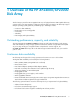
1 Overview of the HP XP24000/XP20000 Disk Array This disk array is part of the HP StorageWorks XP series of high-performance RAID-capable disk array systems used to store large quantities of data in an efficient and secure manner. XP disk arrays support multiple operating systems, platforms, and RAID groups.
NOTE: Although access to data is not compromised, the failure of a key component can cause a temporary reduction in disk array performance.
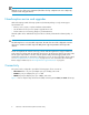
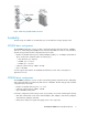
Figure 1 Disk array simplified SAN connection . Scalability The disk arrays are scalable to accommodate your current and future storage capacity needs. XP24000 basic configuration The XP24000 configuration consists of a disk control frame (primary rack) that can have 128HDDs and zero to 4 disk array frames (DKU) that can each have 256 HDDs for a total of 1152 hard drives.
• One 60-disk chassis Adding storage You can add more disk chassis in this order: R0, R1, R2, and R3. Each disk chassis contains 60 hard disk drives. Your HP support representative can add disk chassis and disk drives online with no interruptions to applications or hosts. Additional details about each rack follow. Primary rack expansion In addition to the basic disk chassis R0, you can expand the disk array in the primary rack as follows: • Add 60-disk chassis R1 to the top space of the primary rack.
Web-based array management The XP disk arrays come with HP StorageWorks XP Remote Web Console, a Java-based interface that runs on the SVP and enables you to manage one disk array. For managing multiple arrays, the optional HP StorageWorks XP Command View Advanced Edition software runs on a Windows-based server and can be accessed using remote web-based clients. These software solutions enable comprehensive disk array management.
• XP Continuous Track software • Remote Web Console software • An XP Disk Array Documentation CD (includes owner's guide, OS configuration guides, and software user guides) • Site preparation services • Installation and configuration services • Proactive support for one year • Reactive hardware support for two years • Software support for one year (included with software title) Required additional components • • • • • Cache memory Shared memory DKA pairs CHA pairs Hard disk drives • HP StorageWorks XP Ar
Name Description Document HP StorageWorks DKA Encryption License Key Enables the user to implement encryption for both open-systems and mainframe data. HP StorageWorks XP24000/XP20000 Disk Encryption User Guide HP StorageWorks XP Thin Provisioning Software Provides “virtual storage capacity” to simplify administration and addition of storage, eliminate application service interruptions, and reduce costs. See the HP StorageWorks XP24000/XP20000 Thin Provisioning Software User Guide.
Name Description Document HP StorageWorks XP External Storage Software Realizes the virtualization of the storage system. Users can connect other storage systems to the XP24000/XP20000 disk array and access the data on the external storage system over virtual devices on the XP24000/XP20000 disk array. Functions such as TrueCopy and Cache Residency can be performed on the external data.
Name Description Document HP StorageWorks Volume Security Allows users to restrict host access to data on the storage system. Mainframe users can restrict host access to LVIs based on node IDs and logical partition (LPAR) numbers.
Name Description Document Hitachi Dataset Replication (Logical Volume Divider) Operates together with the XP Business Copy feature. Rewrites the OS management information (VTOC, VVDS, and VTOCIX) and dataset name and creates a user catalog for a XP Business Copy target volume after a split operation. Provides the prepare, volume divide, volume unify, and volume backup functions to enable use of an XP Business Copy target volume.
Name HP StorageWorks XP Performance Advisor Software Description Document Collects, monitors, and displays in-depth performance data at the component level (LDEV, CHA, DKA, and DKC). Includes XPWatch, a real-time troubleshooting tool to identify the root cause of performance issues.
Overview of the HP XP24000/XP20000 Disk Array
2 Hardware description of the HP XP24000/XP20000 Disk Array The HP StorageWorks XP series of disk arrays are high-performance RAID-capable disk array systems used to store large quantities of data in an efficient and secure manner. There are no single points of failure in the disk arrays. They include redundant logic assemblies, controllers, power supplies, and dual-ported RAID disk drives, all of which can be removed or replaced without interrupting access to data.
Figure 2 XP24000 system architecture . XP20000 system architecture Figure 3 shows, the basic XP20000 disk array consists of three main sections: the power supply, a DKC, and a DKU. The power supply section consists of the AC-DC power supplies and battery boxes. The DKC consists of the channel adapters (CHAs), disk adapters (DKAs), cache memory adapters (CMAs), and shared memory adapters (SMAs). The DKU consists of the disk drives and Fibre Channel switches (FSW, not shown).
Figure 3 XP20000 system architecture . Physical assemblies The XP24000 disk array includes the following major hardware assemblies (see Figure 4): • One disk control frame (DKC) • Zero to four disk array frames (DKUs) To monitor and manage the array, a management server supplied by the customer is also required. The following figure shows the disk array with the maximum of four DKUs. The DKC alone constitutes the minimum configuration. Figure 4 Disk array frames .
Disk control frame The DKC controls the disk array. It contains the control panel, connection hardware, power supplies, SVP, and control boards for the disk array. It also contains up to 128 disk drives for the XP24000 and contains up to 120 disk drives for the XP20000. DKC clusters As the following figure shows, power and PCBs in the DKC are organized into two independent and redundant clusters.
Unit emergency power off switch The UNIT EMERGENCY POWER OFF switch is located on the back of the DKC cabinet. For more information about this switch, see “Emergency power off” on page 39.
Figure 6 Disk drive installation in the HDU box . Figure 7 shows how the disk adapters connect to the HDUs in a fully expanded system. Figure 7 DKA and HDU interconnections . RAID options The disk array supports RAID1 (2D+2D or 4D+4D), RAID5 (3D+1P or 7D+1P), and RAID6 (6D+2P) array groups. RAID levels may be intermixed, as illustrated by Figure 8.
Figure 8 Intermixed RAID groups . Backup batteries The XP24000/XP20000 disk arrays use batteries and two modes of backup operation to provide backup power protection for cache memory, shared memory, the DKAs, CHAs, and disk drives. If AC input power is lost, the disk array continues normal operation for 200 ms or 1 minute, depending on whether the disk array is set for Backup Mode or De-stage Mode. See Figure 9.
Figure 9 Battery de-staging and backup modes . When AC power is restored, the disk array powers on again automatically if the AUTO POWER-ON jumper is set to ENABLE. If the jumper is set to DISABLE, the disk array must be manually powered on again using the control panel PS ENABLE and PS ON/OFF switches. Before installation HP representatives will help you determine the best battery mode and power-on mode for your configuration and will configure the selected mode for you.
Feature Maximum storage capacity (not including external storage) Cache Specification 332 TB (where 1 TB = 1012 bytes) (Usable storage is always less than the maximum raw storage capacity.) 4 to 512 GB • 73 GB 15000 RPM FC • 73 GB Solid State • 146 GB 15000 RPM FC • 146 GB Solid State • 200 GB Solid State • 300 GB 10000 RPM FC Hard disk and flash drives • 300 GB 15000 RPM FC • 400 GB Solid State • 750 GB 7200 RPM SATA • 400 GB 10000 RPM FC • 1TB 7.
Feature Specification LUNs per port Up to 1024 Table 5 XP20000 selected hardware specifications Feature Specification Power Single-phase, 50 or 60 Hz DKC/DKU One XP20000 DKC, zero to one XP20000 DKU Maximum hard disk drives 240 Maximum spare disk drives 16 Maximum array groups/subsystem 287 Maximum storage capacity (excluding external storage) Cache 69.2 TB (where 1 TB = 1012 bytes) (Usable storage is always less than the maximum raw storage capacity.
Feature Specification SVP code XP20000-specific High-availability secondary SVP Optionally available • RAID1 (2D+2D) • RAID1 (4D+4D) RAID level • RAID5 (3D+1P) • RAID5 (7D+1P) • RAID6 (6D+2P) LDEVs Up to 64K LUNs per port Up to 1024 Temperature specifications Table 6 XP24000/XP20000 temperature specifications Temperature range type Range Recommended operating temperature range 21 to 24 degrees C, 70 to 75 degrees F Operating temperature 16 to 32 degrees C, 61 to 89 degrees F Nonoperating t
Humidity range type Noncondensing relative humidity (RH) Shipping and storage humidity range (product packed in factory packing) 5% to 95% Mechanical vibration specifications Maximum operating acceleration is 0.05G at a frequency range of 10 to 300 Hz. XP24000/XP20000 AC line voltage requirements Each DKC or DKU has two or four power cords. In case of a failure of the power source for one cord, the power requirements, and therefore the current requirement for the remaining power cord, will double.
Parameter Number of circuit breakers 200 VAC 50/60 Hz 208 VAC 60 Hz 220 VAC 50 Hz 230 VAC 50/60 Hz 240 VAC 50 Hz 4 4 4 4 4 Table 10 XP24000 DKC power specifications for 30-amp, 50 or 60 Hz, three-phase Parameter Number of power cords Recommended circuit breakers Number of circuit breakers 200 VAC 50/60 Hz 208 VAC 60 Hz 220 VAC 50 Hz 230 VAC 50/60 Hz 240 VAC 50 Hz 380 VAC 50 Hz 400 VAC 50 Hz 415 VAC 50 Hz 2 2 2 2 2 2 2 2 30A 30A 30A 30A 30A 30A 30A 30A 2 2 2 2 2 2 2
Parameter Number of circuit breakers 200 VAC 50/60 Hz 208 VAC 60 Hz 220 VAC 50 Hz 230 VAC 50/60 Hz 240 VAC 50 Hz 4 4 4 4 4 Table 13 XP24000 DKU power specifications for 30-amp, 50 or 60 Hz, three-phase Parameter Number of power cords Recommended circuit breakers Number of circuit breakers 200 VAC 50/60 Hz 208 VAC 60 Hz 220 VAC 50 Hz 230 VAC 50/60 Hz 240 VAC 50 Hz 380 VAC 50 Hz 400 VAC 50 Hz 415 VAC 50 Hz 2 2 2 2 2 2 2 2 30A 30A 30A 30A 30A 30A 30A 30A 2 2 2 2 2 2 2
3 Operating the HP XP24000/XP20000 Disk Array During normal operations, the disk array does not require your intervention and you should not attempt to open the disk array cabinets. The disk array reports any service information messages (SIMs) to the SVP and the Device Manager server. If the array is set up for remote support using either the modem or Internet option, the SVP automatically reports SIMs to the HP Storage Technology Center (STC).
CAUTION: Disk array maintenance must be done only by trained and qualified HP support representatives. Only an HP support representative can power off the disk array, except in an emergency. CAUTION: Do not perform any procedures not described in this guide. If you have any questions or concerns, contact your HP support representative. WARNING! Do not touch areas marked HAZARDOUS, even with the power off. These areas contain high-voltage power.
Managing the disk array The Remote Web Console software allows browser-based management of a single disk array. You can install the optional HP StorageWorks XP Array Manager software and the HP StorageWorks Command View XP Advanced Edition software on an optional management server to enable additional management capabilities, including the ability to manage multiple arrays. You can also install other HP StorageWorks XP Disk Array software on the management server.
Control panel and LED descriptions Once the disk array is powered on and running normally, no user operations are required at the control panel, except when you are instructed by your HP support representative. Figure 11 shows the control panel location and layout. Table 16 explains the control panel functions. Figure 11 Control panel and LED descriptions . Table 16 Control panel control and LED descriptions Item Label Indicator Description During normal operation, this LED should be on.
Item Label Indicator Description During normal operation, this LED should be off. • ON: One or more of the following: • DKC DC power is under voltage. • DC power is over current. 2 SUB-SYSTEM ALARM • The temperature is abnormally high. LED (Red) • An unrecoverable failure has occurred. If the disk array is set up for remote support, your HP support representative is notified automatically.
Item Label Indicator Description During normal operation, this LED should be on. 8 BS-ON LED (Amber) • ON: The disk array is plugged in and receiving power from the primary AC outlet. The SVP is receiving power from the outlet. • OFF: The disk array is not receiving power from the primary AC outlet. Check the electrical outlets in your building. During normal operation, this LED should be on. 9 PS-ON LED (Green) • ON: The PS ON/OFF switch is on.
Planned power off Occasionally, you may need to plan a site power outage, such as during alterations to the data center, inspections, or work by the electric company. If a scheduled power outage will affect the disk array, contact your HP support representative to schedule a planned power off. CAUTION: Only a trained HP support representative can shut down and power off the disk array. Do not attempt to power down the disk array other than during an emergency.
2. Pull the switch up and then out towards you. The disk array shuts down immediately. The UNIT EMERGENCY POWER OFF switch mechanically locks itself in the off position to prevent anyone from restoring power in a potentially hazardous situation. WARNING! The UNIT EMERGENCY POWER OFF switch provides only partial power off capability. AC input power remains present at the primary circuit. 3. When the emergency situation is over, call the HP technical support center.
2. Move the PS ON/OFF switch to the ON position. The following LED power sequence occurs: • BS-ON turns amber. • PS-ON turns green. • SUB-SYSTEM MESSAGE may turn amber if the disk array is not configured for remote support. This indicates the system has produced a service information message because of the power outage. • SUB-SYSTEM READY turns green, signifying the system is ready. CAUTION: Powering on the disk array can take up to 10 minutes and is complete only when the SUB-SYSTEM READY LED turns green.
Operating the HP XP24000/XP20000 Disk Array
4 Troubleshooting the HP XP24000/XP20000 Disk Array Service information messages The system generates service information messages (SIMs) to identify normal operations, service requirements, and failures. SIMs are generated by the SVP and the system microprocessors. Your HP support representative uses the SIMs to monitor and troubleshoot the system as explained below. You can view SIMs using the system's management software.
24x7 to ensure maximum system availability by providing intelligent event diagnosis, and automatic, secure submission of hardware event notifications to HP, which will initiate a fast and accurate resolution, based on your product’s service level. Notifications may be sent to your authorized HP Channel Partner for on-site service, if configured and available in your country. The HP Insight Remote Support products available for the XP24000/XP20000 disk arrays are described in Table 17 on page 44.
HP Product AE245A Description Application HP XP No Mission Critical No LAN Support For a customer whose strict security protocols specifically prohibit inbound/ outbound traffic to/from the data center and thus will not allow Remote Support connection by either modem or LAN and does not have a Mission Critical Services on-site contract. The added cost of this configuration only covers the additional warranty support cost to HP during warranty period.
2. The failure is reported to the system. 3. The system stores the failure information in the system log. 4. The generated SIMs are stored on the system for use by HP technical support representatives, and logged on the management server as remote SIMs (R-SIMs). If the system is not set up for remote support, when a SIM is generated, the amber message LED on the system control panel turns on. Call HP to determine the reason for the message. 5.
5 Support and other resources Related documentation The following documents provide related information: • HP StorageWorks XP24000/XP20000 Disk Array Site Preparation Guide • HP StorageWorks XP24000/XP20000 Remote Web Console User Guide • HP StorageWorks XP Disk Array Mainframe Host Attachment and Operations Guide You can find these documents on the HP Manuals website: http://www.hp.com/support/manuals In the Storage section, click Disk Storage Systems and then select a product.
WARNING! To reduce the risk of personal injury or damage to equipment: • • • • • Extend leveling jacks to the floor. Ensure that the full weight of the rack rests on the leveling jacks. Install stabilizing feet on the rack. In multiple-rack installations, fasten racks together securely. Extend only one rack component at a time. Racks can become unstable if more than one component is extended.
6 Regulatory statements for the HP XP24000/XP20000 Disk Array FCC EMC statement (USA) This equipment has been tested and found to comply with the limits for a Class A digital device, pursuant to Part 15 of the FCC rules. These limits are designed to provide reasonable protection against harmful interference when the equipment is operated in a commercial environment.
IEC statement (worldwide) This is a Class A product. In a domestic environment this product may cause radio interference, in which case the user may be required to take adequate measures. EMC statement (Canada) This Class A digital apparatus meets all requirements of the Canadian Interference-Causing Equipment Regulations. Cet appareil numérique de la Classe A respecte toutes les exigences du Règlement sur le matériel brouilleur du Canada.
Harmonics conformance (Japan) German noise declaration XP24000/XP20000: Schalldruckpegel Lp = 70 dB(A) Am Arbeitsplatz (operator position) Normaler Betrieb (normal operation) Nach ISO 7779:1988 / EN 27779:1991 (Typprüfung) Laser safety When equipped with native Fibre Channel adapters, this product contains a laser internal to the Optical Link Module (OLM) contained on the Channel Adapter boards for connection to a fibre communications network.
European WEEE statements Czech Danish Dutch English 52 Regulatory statements for the HP XP24000/XP20000 Disk Array
Estonian Finnish French German XP24000/XP20000 Disk Array Owner Guide 53
Greek Hungarian Italian Latvian 54 Regulatory statements for the HP XP24000/XP20000 Disk Array
Lithuanian Polish Portuguese Slovak XP24000/XP20000 Disk Array Owner Guide 55
Slovenian Spanish Swedish 56 Regulatory statements for the HP XP24000/XP20000 Disk Array
Glossary ACP Array control processor. AL Arbitrated loop. AL-PA Arbitrated loop physical address. allocation The ratio of allocated storage capacity versus total capacity as a percentage. Allocated storage refers to those logical devices (LDEVs) that have paths assigned to them. Allocated storage capacity is the sum of the storage of these LDEVs. Total capacity is the sum of the capacity of all LDEVs on the disk array.
disk array supports a certain number of CUs, depending on the disk array model. Each CU can manage multiple LDEVs. Therefore, to uniquely identify a particular LDEV requires both the CU number and the LDEV number. CSR Customer Self Repair. C-Track Continuous track. An HP StorageWorks software program that detects internal hardware component problems on a array and automatically reports them to the HP Storage Technology Center (STC). CU Control unit. CVS Custom volume size.
failover An operation that reverses replication direction so that the destination becomes the source and the source becomes the destination. Failovers can be planned or unplanned and can occur between DR groups, managed sets, fabrics or paths, and array controllers. FC Fibre Channel. A network technology primarily used for storage networks. FC-AL Fibre Channel arbitrated loop. FCP Fibre Channel protocol.
mirroring consistency The consistency (usability) of data in a volume (for example, S-VOL). MIX A circuit board in the disk control unit that includes disk adapters and channel adapters for interfacing disk drives and the host to cache memory. MR Magnetoresistive. ms, msec Millisecond. mutual hot standby system Two servers that are poised to cover for each other if necessary. NAS Network attached storage. node Logically speaking, an environment where instances can be executed.
family members. Consult the owner’s guide or your HP representative for the details about which RAID levels are supported by your specific XP disk array. RS Russellstoll (registered trademarked), a brand of electrical plugs and receptacles manufactured by Thomas & Betts Corporation. R-SIM Remote service information message. R/W, r/w Read/write. SAN Storage area network. A network of storage devices available to one or more servers. script file A file containing a shell script.
Glossary
Index A AC line voltage, 30 AC power cords, 30 array management, 11 automatic restart, 41 B backup battery operation mode, 25 batteries, backup, 25, 40 C C-Track, 7, 8, 37, 43, 46 cache battery backup, 25 Command View XP Advanced Edition, 11, 35 Command View XP Advanced Edition, 11, 35 components hardware, 21 included, 11 required additional, 12 connectivity, 8 control panel, 36, 38 customer self repair, 47 D data integrity, 7 data availability, 7 destage battery operation mode, 25 disk array features ha
HP Insight Remote Support Advanced, 8 HP Storage Technology Center. See STC, 8 humidity specifications, 30 I Internet-based remote support, 43 L LED Control Panel Descriptions, 36 displayed with SIM, 46 during restart, 40, 41 during restart, 40, 41 line voltage, 30 M maintenance, remote, 37 management server, 21, 35 manual restart, 40 mechanical vibration specifications, 30 N normal operations, 33 O operating systems, 11 P physical components.
X XP Continuous Track, 7, 8, 37, 43, 46 XP Continuous Track, 7, 8, 37, 43, 46 XP24000/XP20000 Disk Array Owner Guide 65