
HP StorageWorks External Storage XP user guide (T1706-96006, June 2006)
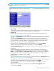
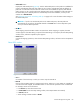
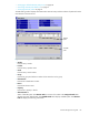
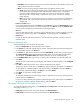
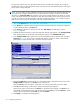
Table Of Contents
- HP StorageWorks External Storage XP user guide
- Contents
- About this guide
- 1 Overview of connecting external arrays
- 2 Preparing for External Storage XP operations
- System requirements
- External Storage XP requirements
- Installing External Storage XP
- Preparing for External Storage XP settings
- Powering arrays on or off
- Using mapped external LUs from the host connected to the local array
- Uninstalling External Storage XP
- Limitations on External Storage XP operations
- Figure 11 Example of external LU with 2 TB or less
- Figure 12 External LU capacity is larger than the specified emulation type’s basic capacity (OPEN-3 example)
- Figure 13 External LU capacity is smaller than the specified emulation type’s basic capacity
- Table 4 When external LU’s emulation type is OPEN
- Table 5 When external LU’s emulation type is for mainframes
- Combining External Storage XP with other HP StorageWorks products
- 3 Managing cache with external storage
- Guidelines for using cache with external storage
- Determining, setting, or changing the external LU cache mode
- Partitioning cache for external storage
- Determining the number and size of needed partitions
- Creating Cache partitions
- Changing storage system modes
- 4 External Storage XP panes
- 5 Configuring external LUs
- Overview of configuring external LUs
- Setting an external array’s port
- Setting a local array’s port attributes
- Mapping external LUs (Add LU)
- Setting alternate paths for external LUs
- Adding alternate paths by selecting multiple external LUs (Add Paths)
- Deleting alternate paths by selecting multiple external LUs (Delete Paths)
- Checking an external LU’s status (LDEV Information)
- Disconnecting external arrays or LUs
- Checking the connection status and resuming external LU operations (Check Paths & Restore Vol.)
- Restoring external LUs (LDEV Restore)
- Stopping the use of paths to an external LU by specifying an external array’s WWN (Disconnect Paths)
- Restoring paths to an external LU by specifying an external array’s WWN (Check Paths)
- Changing an external array’s port setting
- Stopping the use of paths to an external LU by specifying a local array’s port (Disconnect Paths)
- Restoring paths to an external LU by specifying a local array’s port (Check Paths)
- Deleting external LU mappings (Delete LU)
- 6 Troubleshooting NAS Blade systems that include external arrays
- 7 Remote command devices
- 8 Troubleshooting External Storage XP
- A Notes on connecting external arrays
- Connecting Thunder 9500V subsystems
- System parameters for connecting Thunder 9500V subsystems
- Relationship between serial numbers in the Device list on the LU Operation pane and Thunder 9500V subsystem models
- Relationship between the WWN of the port on the Thunder 9500V subsystem and the controller
- Path status and examples of recovery procedures (Thunder 9500V subsystems)
- Connecting TagmaStore AMS and TagmaStore WMS subsystems
- System parameters for connecting TagmaStore AMS and TagmaStore WMS subsystems
- Relationship between serial numbers in the Device list on the LU Operation pane and TagmaStore AMS and TagmaStore WMS subsystem models
- Relationship between the WWN of the port on the TagmaStore AMS or TagmaStore WMS subsystem and the controller
- Path status and examples of recovery procedures (TagmaStore AMS and TagmaStore WMS subsystems)
- Connecting XP12000/XP10000 Disk Arrays
- Connecting XP1024/XP128 Disk Arrays
- Connecting XP512/XP48 Disk Arrays
- Connecting HP 200 Storage Virtualization System as external storage
- Connecting EVA arrays
- Connecting Thunder 9500V subsystems
- B Required volume capacity for emulation types
- C Adjusting volume capacity for copy pair setting
- D Using an XP12000/XP10000/SVS200 with an EVA3000/5000 external storage
- E Configuring MSA1000/1500 as external arrays
- Index

84 Configuring external LUs
For this example, LDEVs created from the first external LU are mapped to 00:00, 00:02, and 00:04,
respectively. The starting CU:LDEV number of LDEVs created from the second external LU is 00:06, and
subsequent LDEVS are mapped to 00:08 and 00:0A. The starting CU:LDEV number of LDEVs created
from the third external LU is 00:0C, and subsequent LDEVs are mapped to 00:0E and 00:10.
• LDEV map
Each cell in the map represents an internal XP CU and LDEV number. Select a cell for the internal LDEV
on the map. The selected cell turns blue, and the LU of the selected cell becomes the first CU:LDEV
number of the mapped destination LUs. Defined (in use) internal LDEVs appear in gray, and internal
LDEVs to be mapped appear in white.
• Clear button
Releases the cell selected on the LDEV map.
• OK button
Closes the Select LDEV window, and returns to the Auto Map Setting window. On the Auto Map Setting
window, the CU:LDEV number you selected on the Select LDEV window as the head CU:LDEV number
of the mapped destination internal LDEVs appears in Start CU:LDEV.
• Cancel button
Cancels all settings in the Select LDEV window, and returns to the Auto Map Setting window.
To map multiple external LUs as internal LDEVs at one time:
1. Select the LU Operation tab. The LU Operation pane appears.
2. In the Device tree, select Discovery. WWNs identifying the external array port that can be connected
appear in the tree.
3. In the Device tree, select the port (WWN) you want to connect from the WWNs displayed. External LUs
that can be connected from the port (WWN) selected in the tree appear in the Device list.
4. In the Device list, select the external LUs you want to map as internal LDEVs, right-click, and select Add
LU (Auto). The Auto Map Setting window (Figure 48) appears.
5. Set the attributes for the external LUs you selected on the Device list.
NOTE: Attributes for all LUs mapped at one time are identical.
• To select the first CU:LDEV number of the mapped destination internal LDEVs and the mapping
interval, go to step 6.
• To let External Storage XP select the first CU:LDEV number, go to step 9.
6. Click Select LDEV. The Select LDEV window appears.
7. Select the first CU:LDEV number of the mapped destination internal LDEVs and the mapping interval.
8. Click OK. The Auto Map Setting window appears.
9. If you do not want to automatically set the primary and alternate paths, but you want to specify the
paths to be set as candidates for the primary and alternate paths, click Select Paths. The Select Paths
window appears.
To automatically set alternate paths, go to step 12.
10.Select the path and exclude it from the list of the candidates for the primary and alternate paths. For
instructions, see ”Mapping external LUs individually (Add LU)” on page 73.
11.Click OK. The Auto Map Setting window appears.
12.Click OK. The Auto Map Setting window closes, and mapping the internal CU:LDEV numbers to the
external LUs starts.
NOTE: If the CU:LDEV numbers cannot be mapped properly because too many external LUs are
selected on the Device list, all processing is canceled and the message pane appears.
• After the CU:LDEV number mapping is complete, if the SSID setting is required, the SSID window
(Figure 46) appears. Go to step 13.