
HP StorageWorks External Storage XP user guide (T1706-96006, June 2006)
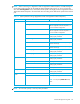
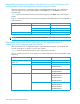
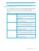
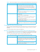
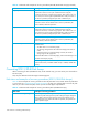
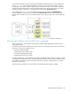

Table Of Contents
- HP StorageWorks External Storage XP user guide
- Contents
- About this guide
- 1 Overview of connecting external arrays
- 2 Preparing for External Storage XP operations
- System requirements
- External Storage XP requirements
- Installing External Storage XP
- Preparing for External Storage XP settings
- Powering arrays on or off
- Using mapped external LUs from the host connected to the local array
- Uninstalling External Storage XP
- Limitations on External Storage XP operations
- Figure 11 Example of external LU with 2 TB or less
- Figure 12 External LU capacity is larger than the specified emulation type’s basic capacity (OPEN-3 example)
- Figure 13 External LU capacity is smaller than the specified emulation type’s basic capacity
- Table 4 When external LU’s emulation type is OPEN
- Table 5 When external LU’s emulation type is for mainframes
- Combining External Storage XP with other HP StorageWorks products
- 3 Managing cache with external storage
- Guidelines for using cache with external storage
- Determining, setting, or changing the external LU cache mode
- Partitioning cache for external storage
- Determining the number and size of needed partitions
- Creating Cache partitions
- Changing storage system modes
- 4 External Storage XP panes
- 5 Configuring external LUs
- Overview of configuring external LUs
- Setting an external array’s port
- Setting a local array’s port attributes
- Mapping external LUs (Add LU)
- Setting alternate paths for external LUs
- Adding alternate paths by selecting multiple external LUs (Add Paths)
- Deleting alternate paths by selecting multiple external LUs (Delete Paths)
- Checking an external LU’s status (LDEV Information)
- Disconnecting external arrays or LUs
- Checking the connection status and resuming external LU operations (Check Paths & Restore Vol.)
- Restoring external LUs (LDEV Restore)
- Stopping the use of paths to an external LU by specifying an external array’s WWN (Disconnect Paths)
- Restoring paths to an external LU by specifying an external array’s WWN (Check Paths)
- Changing an external array’s port setting
- Stopping the use of paths to an external LU by specifying a local array’s port (Disconnect Paths)
- Restoring paths to an external LU by specifying a local array’s port (Check Paths)
- Deleting external LU mappings (Delete LU)
- 6 Troubleshooting NAS Blade systems that include external arrays
- 7 Remote command devices
- 8 Troubleshooting External Storage XP
- A Notes on connecting external arrays
- Connecting Thunder 9500V subsystems
- System parameters for connecting Thunder 9500V subsystems
- Relationship between serial numbers in the Device list on the LU Operation pane and Thunder 9500V subsystem models
- Relationship between the WWN of the port on the Thunder 9500V subsystem and the controller
- Path status and examples of recovery procedures (Thunder 9500V subsystems)
- Connecting TagmaStore AMS and TagmaStore WMS subsystems
- System parameters for connecting TagmaStore AMS and TagmaStore WMS subsystems
- Relationship between serial numbers in the Device list on the LU Operation pane and TagmaStore AMS and TagmaStore WMS subsystem models
- Relationship between the WWN of the port on the TagmaStore AMS or TagmaStore WMS subsystem and the controller
- Path status and examples of recovery procedures (TagmaStore AMS and TagmaStore WMS subsystems)
- Connecting XP12000/XP10000 Disk Arrays
- Connecting XP1024/XP128 Disk Arrays
- Connecting XP512/XP48 Disk Arrays
- Connecting HP 200 Storage Virtualization System as external storage
- Connecting EVA arrays
- Connecting Thunder 9500V subsystems
- B Required volume capacity for emulation types
- C Adjusting volume capacity for copy pair setting
- D Using an XP12000/XP10000/SVS200 with an EVA3000/5000 external storage
- E Configuring MSA1000/1500 as external arrays
- Index
132 Notes on connecting external arrays
Relationship between serial numbers in the Device list on the LU Operation pane
and TagmaStore AMS and TagmaStore WMS subsystem models
When the external array is a TagmaStore AMS or TagmaStore WMS subsystem, you can identify the
subsystem model from the serial number displayed in the Serial column in the Device list on the LU
Operation pane.
Table 18 shows the relationship between serial numbers displayed in the Serial column and subsystem
models.
NOTE: In serial numbers, X is an arbitrary number or character.
Relationship between the WWN of the port on the TagmaStore AMS or
TagmaStore WMS subsystem and the controller
When the external array is a TagmaStore AMS or TagmaStore WMS subsystem, you can identify the
controller (controller 0 or controller 1) from the port’s WWN.
Table 19 shows the relationship between the port’s WWN and the controller.
Table 18 Relationship between serial numbers and subsystem models (TagmaStore AMS and TagmaStore
WMS subsystems)
Storage subsystem Displayed serial number Model
AMS 77XXXXXX AMS 1000
75XXXXXX AMS 500
73XXXXXX AMS 200
WMS 71XXXXXX WMS 100
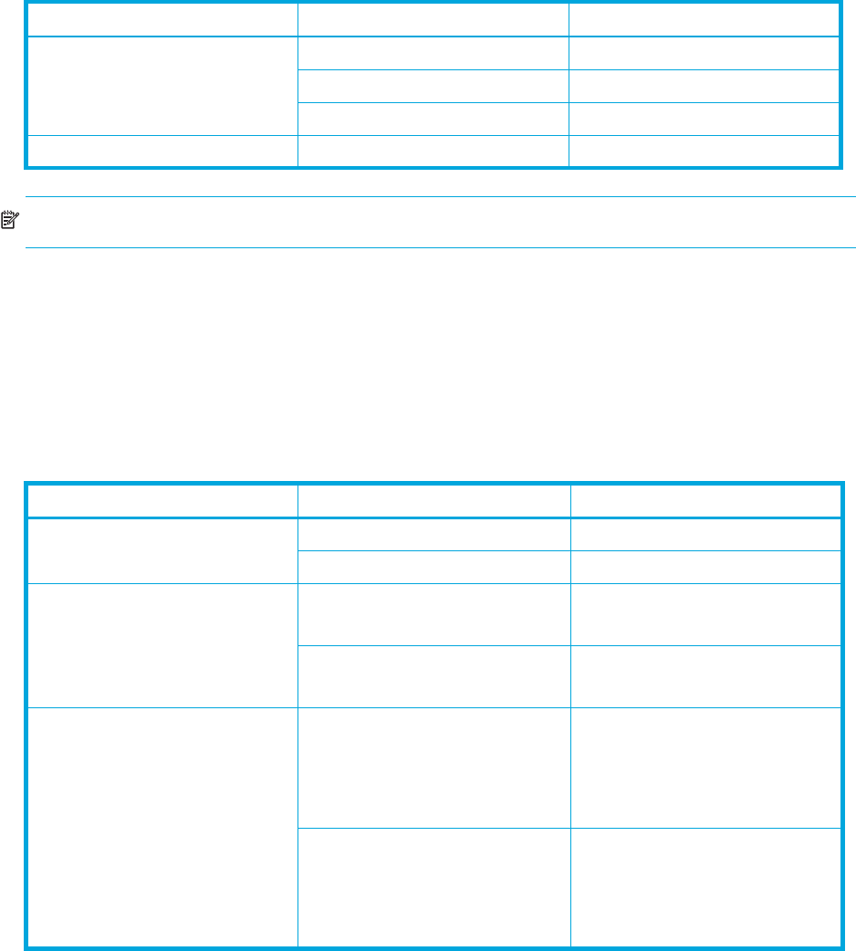
Table 19 Relationship between ports’ WWNs and controllers (TagmaStore AMS and TagmaStore WMS
subsystems)
Model Controller Port’s WWN
AMS 200
WMS 100
Controller 0 XXXXXXXXXXXXXXX0
Controller 1 XXXXXXXXXXXXXXX1
AMS 500 Controller 0 XXXXXXXXXXXXXXX0
XXXXXXXXXXXXXXX1
Controller 1 XXXXXXXXXXXXXXX2
XXXXXXXXXXXXXXX3
AMS 1000 Controller 0 XXXXXXXXXXXXXXX0
XXXXXXXXXXXXXXX1
XXXXXXXXXXXXXXX2
XXXXXXXXXXXXXXX3
Controller 1 XXXXXXXXXXXXXXX4
XXXXXXXXXXXXXXX5
XXXXXXXXXXXXXXX6
XXXXXXXXXXXXXXX7