HP Hitachi Universal Replicator™ for Mainframe User Guide HP XP24000 Disk Array, HP XP20000 Disk Array Abstract This document describes and provides instructions for using the Hitachi Universal Replicator™ for Mainframe software to configure and perform operations on the HP XP storage system.
© Copyright 2007, 2010 Hewlett-Packard Development Company, L.P. Confidential computer software. Valid license from HP required for possession, use or copying. Consistent with FAR 12.211 and 12.212, Commercial Computer Software, Computer Software Documentation, and Technical Data for Commercial Items are licensed to the U.S. Government under vendor's standard commercial license. The information contained herein is subject to change without notice.
Contents 1 Overview of Universal Replicator for Mainframe.............................................8 Universal Replicator for Mainframe.............................................................................................8 Features..................................................................................................................................9 Benefits...................................................................................................................................
Command Device..............................................................................................................46 3 Preparing for Universal Replicator for Mainframe Operations.........................47 Requirements and Restrictions for Universal Replicator for Mainframe.............................................47 System Requirements..........................................................................................................47 Disk Track Format..................................
Compatible FlashCopy V2..................................................................................................97 Planning for Journal Volumes....................................................................................................99 Why Planning is Necessary?...............................................................................................99 What to Consider for Planning........................................................................................
Powering Off the Primary and Secondary Storage Systems at the Same Time......................154 Powering Off Network Relay Devices.............................................................................155 Powering On the Primary Storage System............................................................................155 Removing the Relationship Between the Primary and the Secondary Storage Systems.....................155 6 Configuring Journal Groups.................................................
Switching Operations to the Secondary Site........................................................................220 Transferring Operations Back to the Primary Site..................................................................221 Resuming Normal Operations at the Primary Site.................................................................222 Disaster Recovery for Multiple Primary and Secondary Storage Systems..................................
1 Overview of Universal Replicator for Mainframe This chapter provides an overview of the Universal Replicator for Mainframe software and describes its features and benefits.
Features Universal Replicator for Mainframe provides the following key features: • • Heterogeneous Storage System Support ◦ Used with the XP disk array, Universal Replicator for Mainframe software enables storage management and disaster recovery in heterogeneous systems, providing maximum flexibility and support of enterprise-class environments.
• • ◦ Reduces overhead and application impact at the production site by placing more of the workload on the remote site ◦ Centralizes operations for management resources and provides secure management of data-related operational risk Improving Operational Efficiency and Resiliency ◦ Simplifies consolidation/aggregation and mapping of data value to the cost of storage ◦ Supports planned site outages ◦ Keeps logging changes in the event of network problems between sites ◦ Reduces costs—requires o
2 About Universal Replicator for Mainframe Operations This chapter provides an overview of Universal Replicator for Mainframe operations: • “Functionality Overview” (page 11) • “Components” (page 13) • “Remote Copy Operations” (page 25) • “Journal Processing” (page 29) • “Universal Replicator for Mainframe Delta Resync Operation” (page 32) • “Journal Obtain in TrueCopy for Mainframe Synchronous Secondary Site” (page 33) • “Switching the Master Journal Group of Universal Replicator for Mainframe
Figure 1 Universal Replicator for Mainframe Components for a Fibre Channel Connection Journal Obtain Journal obtain is the function to store the already stored data in the primary data volume as a base-journal in the journal volume at the primary site. This function then stores the write data as a journal data in the journal volume with every update of the primary data volume according to the write instruction from the host.
consistency between the primary and secondary data volumes. After the journal data are restored to the secondary data volume, the journal data are discarded at the secondary site. Components Universal Replicator operations involve the XP disk arrays at the primary and secondary sites, the physical communications paths between these storage systems, and the XP disk array Universal Replicator for Mainframe remote console software.
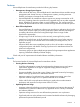
Figure 3 Connection Configuration of Plural Secondary Storage Systems This Universal Replicator for Mainframe components illustration describes: • Storage system • Logical DKC • Main and remote control units (primary storage systems and secondary storage systems) • journal group • Data volume pair • Journal volume • Remote copy connections • Initiator ports and RCU target ports • Universal Replicator remote console software • Host I/O time stamping function • ERC XP Storage Systems Un
Table 1 System Option Modes Mode Description 20 Mode 20 ON: Enables the read option and VOLSER of the suspended secondary data volume to be updated. Mode 20 OFF: Normal operations are performed. 190 Mode 190 ON: By setting both this mode and the mode 20 to ON, you can update the VOLSER and VTOC of the suspended secondary data volume. Mode 190 OFF: Normal operations are performed.
Table 1 System Option Modes (continued) Mode Description Mode 511 ON: The upper limit of the usage rate of the journal data in the journal volume is 40%. Mode 511 OFF: The upper limit of the usage rate of the journal data in the journal volume is 70%. 530 To change the displayed consistency time (C/T) when the Universal Replicator for Mainframe pair status is Duplex, set this mode to ON.
Universal Replicator for Mainframe Software Remote Web Console software includes Universal Replicator for Mainframe for the storage system. The Remote Web Console software communicates with the SVP of each storage system via defined TCP/IP connections. For further information on Remote Web Console operations, see the HP XP24000/XP20000 Remote Web Console User's Guide, or contact your HP account team. The Remote Web Console computer at the primary site must be attached to the primary storage system.
NOTE: When you configure a Universal Replicator for Mainframe journal group pair, you have to specify the serial numbers of the primary storage systems and secondary storage systems. You have to specify different serial numbers for the primary storage system and secondary storage system for the same Universal Replicator for Mainframe journal group pair. If you have to specify the same serial number, contact your HP account team. LDKC The storage system is capable of having up to 510 CUs configured.
Any Fibre Channel interface port on the XP storage system can be configured as an initiator port. The initiator ports cannot communicate with the host processor channels. The host channel paths must be connected to a Fibre Channel interface port other than the initiator port. NOTE: Two or more initiator ports must be configured before you can add the secondary storage systems and create the Universal Replicator for Mainframe volume pairs.
The Number of Journal Volumes One journal group can contain up to 64 journal volumes. Each of the journal volumes can have different volume sizes and different RAID configurations. Journal data will be stored sequentially and separately into each journal volume in the same journal group. Specifications of Journal Volumes • Types of LUs. DKU emulation types that are allowed for journal volumes are shown in “Emulation Types for Journal Volumes” (page 20).
metadata area usable, you need to split (suspend) all the data volume pairs in the journal group and then restore (resynchronize) the pairs. Adding journal volumes during a remote copy operation will not decrease the metadata usage rate if the metadata usage rate is high. Adding journal volumes during a remote copy operation may not change the journal data usage rate until the journal volumes are used.
group are also called the primary data volumes. The journal volumes in the master journal group are called the master journal volumes. The data volumes in the restore journal group are similarly called the secondary data volumes. The journal volumes in the restore journal group are called the restore journal volumes. The data update sequence from the host is managed per the journal group.
2. ◦ In journal group 3, the latest time stamp is 15:03. ◦ In journal group 4, the latest time stamp is 15:04. Universal Replicator for Mainframe searches for the oldest time stamp from the ones identified in step 1 and restores data up to that time to the secondary volumes. In the example shown in Figure 4 (page 23), the oldest time stamp is 15:00. Universal Replicator for Mainframe restores all data that have a time stamp 15:00 or earlier to the secondary data volumes.
– If a pair in journal group 3 is suspended, the consistency time will be 14:03. – If a pair in journal group 4 is suspended, the consistency time will be 14:04 If a failure occurs in a primary storage system and then you want to recover from the failure, restore journal data with time stamps later than the consistency time of the extended consistency group to the secondary data volumes.
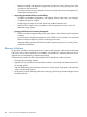
Remote Copy Operations The following figure illustrates the two types of Universal Replicator for Mainframe remote copy operations: initial copy and update copy.
data volume pair is suspended, the status of data that is updated from the host to the primary and secondary data volumes is recorded to the difference bitmap. The base-journal data of primary storage system is stored on the secondary storage system journal volume according to the read command from the secondary storage system. After that, the base-journal data is restored from the journal volume to the secondary data volume. The initial copy operation will finish when all base-journals are restored.
Journal Group Operations Universal Replicator for Mainframe journal groups enable update sequence consistency to be maintained across a journal group of volumes. The primary data volumes and secondary data volumes of the pairs in a journal group must be located within one physical primary storage system and one physical secondary storage system (1-to-1 requirement).
Journal Group Operations Universal Replicator for Mainframe provides the following group-based operations to simplify and expedite disaster or failure recovery procedures: • • Group operations at the primary storage system ◦ Split all pairs in a journal group. For a description of the Group option, see “Splitting a Mirror (Suspending a Copy Operation)” (page 172). ◦ Resume all suspended pairs in a journal group.
NOTE: When you issue the DEVSERV command to the Universal Replicator for Mainframe secondary data volume, INDETERMINATE FAILING UNIT is returned, if the status of Universal Replicator for Mainframe secondary data volume is online. INTERVENTION REQUIRED is returned, if the status of Universal Replicator for Mainframe secondary data volume is offline. Secondary Data Volume Write Option For additional flexibility, Universal Replicator for Mainframe provides a secondary data volume write option (S-Vol.
system to maintain update consistency of the Universal Replicator for Mainframe secondary data volumes.
data in FBA format using a single channel command. The primary storage system can send several journal data using a single RIO, even if their sequence numbers are not contiguous. Therefore, the journal data are usually sent to the secondary storage system in a different order than the journal data were created at the primary storage system. The secondary storage system ensures that the journal data are applied to the secondary data volume in the correct sequence.
Figure 6 Selecting and Settling the Journal at the Secondary Storage System The secondary storage system settles and restores the journal data to the secondary data volume as follows: • Journal data stored in the cache The journal data is copied to the corresponding cached track and promoted to formal data. • Journal data stored in the restore journal volume The journal data is read from the restore journal volume to cache.
Journal Obtain in TrueCopy for Mainframe Synchronous Secondary Site When a failure occurs, before performing the delta resync operations, you need to obtain the journal data in the TrueCopy for Mainframe Synchronous secondary site of the 3DC multi-target configuration.
As shown in Figure 7 (page 33), a Universal Replicator for Mainframe pair created with the delta resync operation is defined as a pair but no copy operation is performed (Hold status). The copy operation is performed when the failure occurs and the delta resync operation is performed. There are several requirements to create a Universal Replicator for Mainframe pair for the delta resync operation, including the need to specify the unused mirror ID.
Figure 8 Delta Resync Setting in 3DC Multi-target Configuration (After Failure Occurred) When a failure occurs in the primary site A as depicted in Figure 8 (page 35), Business Continuity Manager is used to change the former TrueCopy for Mainframe Synchronous secondary site to the primary site B. When performing the delta resync operation in this situation, the Universal Replicator for Mainframe pair for the delta resync operation (as shown in Figure 7 (page 33)) will be synchronized and usable.
The status of the Universal Replicator for Mainframe pair will change to Duplex, not Pending Duplex. This is because delta resync operation uses journal copy to copy only the necessary data. Because of this efficiency, compared to the usual way that copies all the data in the primary data volume, the delta resync operation takes less time to recover a Universal Replicator for Mainframe pair after a failure occurs.
A volume which is not assigned to a Universal Replicator for Mainframe data volume pair has the status simplex. When a Universal Replicator for Mainframe data volume pair is started, the primary storage system changes the status of the primary data volume and secondary data volume to pending duplex. When the initial copy operation is complete, the primary storage system changes the status of both data volumes to duplex.
installed and operational for the XP disk array, this SIM results in an SNMP trap which indicates the reason for suspension. • Universal Replicator for Mainframe Pair Status The Universal Replicator for Mainframe Suspending and Deleting (release) transitional states occur when a request to change the Universal Replicator for Mainframe pair status has been accepted, but the change to the requested status (suspended or simplex) is not yet complete. These states are not reported to the host.
Table 5 Universal Replicator for Mainframe Data Volume Pair Status (continued) Pair Status Description for Mainframe data volume pair, its status will change to pending duplex. Pending Duplex The initial copy operation for this pair is in progress. This data volume pair is not yet synchronized. When the initial copy is complete, the status changes to duplex. Duplex This data volume pair is synchronized. Updates to the primary data volume are duplicated on the secondary data volume.
Table 5 Universal Replicator for Mainframe Data Volume Pair Status (continued) Pair Status Description changing pair option operation are allowed operations on the pairs in the Holding status. This status is displayed when the environment of the delta resync operation to support remote command devices is used. If you execute the delta resync operation on the pair in the Holding status, the operation may fail.
A Universal Replicator for Mainframe pair is suspended by the primary storage system when the following suspension conditions are detected. A Universal Replicator for Mainframe pair can also be suspended by the secondary storage system (see “Suspension Condition” (page 42)).
Table 6 Suspend Types (continued) Suspend Type Applies to Description MCU IMPL Primary data volume, secondary data volume The primary storage system could not find valid control information in its nonvolatile memory during the IMPL procedure. This condition occurs only if the primary storage system is completely without power for more than 48 hours (for example, power failure and fully discharged backup batteries).
Table 8 Universal Replicator for Mainframe Suspension Condition Suspension Condition The secondary storage system could not copy the journal data successfully due to a hardware failure or logic error. Detected by: Universal Replicator for Mainframe Pairs to be Suspended RCU All Universal Replicator for Mainframe secondary data volumes in the journal groups, or the affected secondary data volume. The secondary storage system detected a logical error RCU while selecting the journal data to be restored.
Table 9 SAID Values for the PATH LINK Parameter (FRONT CL1) Package Location Port SAID Package Location Port SAID Package Location Port SAID Package Location Port SAID 1EU CL1-A X'0000' 1GU CL1-J X'0008' 1KU CL9-N X'008C' 1BU CL9-E X'0084' (Basic) CL3-A X'0020' (Add4) CL3-J X'0028' (Add10) CLB-N X'00AC' (Add14) CLB-E X'00A4' CL5-A X'0040' CL5-J X'0048' CLD-N X'00CC' CLD-E X'00C4' CL7-A X'0060' CL7-J X'0068' CLF-N X'00EC' CLF-E X'00E4' CL1-B X'0001' CL1-K
3 In the case of an XP20000 Disk Array, the name of the package location is 1H. 4 In the case of an XP20000 Disk Array, the name of the package location is 1A.
1 In the case of an XP20000 Disk Array, the name of the package location is 2L. 2 n the case of an XP20000 Disk Array, the name of the package location is 2E. 3 In the case of an XP20000 Disk Array, the name of the package location is 2K. 4 In the case of an XP20000 Disk Array, the name of the package location is 2F. Command Device To use Business Continuity Manager, you must set the command device for it separately from the command device for an open system.
3 Preparing for Universal Replicator for Mainframe Operations This chapter describes Universal Replicator for Mainframe operations involving the XP primary and secondary storage systems, the remote copy connections between the primary/secondary storage systems, and the host(s) at the primary and secondary sites, as well as the licensed Universal Replicator for Mainframe remote console software.
NOTE: Universal Replicator for Mainframe can coexist with HP XP Continuous Access Journal in the same storage system. • • Remote copy connections − Fibre Channel (see “Setting up Remote Copy Connections” (page 60)): ◦ Multimode or single-mode optical fibre cables are required at both the primary storage system and secondary storage system. ◦ For distances up to 0.5 km, multimode optical shortwave fiber cables are required between the primary storage system and secondary storage system.
Figure 9 z/Linux Use: Configuration Example of the Case When the Consistency is not Maintained Contact your HP support representative for the latest information on platform support for Universal Replicator for Mainframe and when you use z/Linux as the host OS. • A computer that runs Remote Web Console (Remote Web Console computer): The Remote Web Console software is required for XP disk array Universal Replicator for Mainframe operations.
• About the license of Universal Replicator for Mainframe: To use Universal Replicator for Mainframe, you must install not only a license for Universal Replicator for Mainframe but also a license for TrueCopy for Mainframe. In addition, you also need a license for HP XP Universal Replicator 4x4 Extended CT if you run a 3DC system.
file are copied to the Universal Replicator for Mainframe secondary data volume, and use Universal Replicator for Mainframe to ensure update sequence consistency across this group of secondary data volume.
Table 12 (page 52) lists the volumes and the volume capacity that can be used for the Universal Replicator for Mainframe data volume and journal volume. Remember that the capacity of the journal volume is not included in the accounting capacity. Table 12 Supported Data Volume and Journal Volume Type Support specifications Data Volume VLL volume Available The volume on which Cache Residency Available Manager setting are made Maximum volume capacity Journal Volume 3380-3 2.377 GB 3380-E 1.
Table 13 Specifications of Volumes That Can Form Pairs Item Support specifications Emulation type Same emulation type. Volume capacity Same capacity. Universal Replicator for Mainframe can copy data between volumes with the same emulation and capacity (for example, 3390-3R to 3390-3R). Universal Replicator for Mainframe also supports the Virtual LVI/LUN feature, enabling you to establish Universal Replicator for Mainframe pairs with custom-size emulation types as well as standard-size emulation types.
Table 16 Number of Cylinders According to Each Emulation Type Emulation type Number of Cylinders 3380-J 885 3380-E 1,770 3380-K 2,655 3390-1 1,113 3390-2 2,226 3390-3 3,339 3390-3R • 3390-9 10,017 3390-L 32,760 3390-M 65,520 H6586-G 1,770 H6586-J 885 H6586-K 2,655 H6588-1 1,113 H6588-3 3,436 H6588-9 10,017 H6588-L 32,760 NF80-E 1,770 NF80-J 885 NF80-K 2,655 The number of the required bitmap areas: The number of bitmap areas to be used by all data volumes that form p
Table 17 Relationship between Additional Shared Memory and Total Number of Bitmap Areas of the Storage System Additional Shared Memory for Universal Replicator for Mainframe Total Number of Bitmap Areas of Storage System No additional shared memory for Universal Replicator for Mainframe 0 Additional shared memory for Universal Replicator for Mainframe is installed 7,424 Extension 1 16,384 Extension 2 32,768 Extension 3 (available only for an XP24000 Disk Array) 44,256 Extension 4 (available only
Table 18 Maximum Number of Pairs According to Each Emulation Type, When Pairs Are Created Without the Use of a VLL Volume (continued) Emulation Type Maximum number of pairs Additional shared memory for Universal Replicator for Mainframe is installed Extension 1 Extension 2 Extension 3 Extension 4 3390-M 824 1,820 3,640 4,917 7,281 H6586-G 7,424 16,384 32,768 32,768 32,768 H6586-J 7,424 16,384 32,768 32,768 32,768 H6586-K 7,424 16,384 32,768 32,768 32,768 H6588-1 7,424 16,384
Journal Group The Universal Replicator for Mainframe journal groups have the following requirements: • Each Universal Replicator for Mainframe pair must be assigned to one and only one journal group. Table 19 (page 57) shows the journal group specifications. Table 19 Journal Group Specifications Item Support specifications Number of journal groups Up to 256 journal groups (No. 0 - 255) per one storage system NOTE: The recommended number of journal groups is up to 16.
of the journal group is applied to the data volume pair. For 3DC configurations, see “TrueCopy for Mainframe Synchronous (3DC Cascading Configuration)” (page 79). • Table 20 (page 58) shows the specifications of the relationship between the data volumes, between the journal volumes, and between the data volumes and journal volumes in a journal group. Table 20 Journal Group Volume Specifications Item Support specifications Emulation type Same emulation type.
Universal Replicator for Mainframe does not allow the secondary data volume to be online (except while the pair is split). If the secondary data volume is online, the Universal Replicator for Mainframe add pair operation will fail.
Setting up Remote Copy Connections The following figure shows the remote copy connection configurations for Universal Replicator for Mainframe operations. The primary storage system and secondary storage system of each Universal Replicator for Mainframe pair must be connected via optical fiber cables. If you use multimode shortwave optical fiber cables, fibre cables up to 1.5 km in length and up to two switches are required for distances greater than 0.5 km.
Figure 11 Direct Remote Copy Connections *To set ports, use LUN Manager and set port topology to: Fabric off, FC-AL. Figure 12 Switch Remote Copy Connection Figure 13 Extender Remote Copy Connection CAUTION: When an MCU and RCU are connected via switches with channel extender and multiple remote copy paths are assembled, the capacity of data to be transmitted may concentrate on particular switches, depending on the configuration and the settings of the switch routing.
Enabling the Universal Replicator for Mainframe Option(s) To operate the Universal Replicator for Mainframe software, a computer for Remote Web Console is required. For further information on Remote Web Console operations, see the HP XP24000/XP20000 Remote Web Console User's Guide, or contact your HP support representative.
secondary storage system, one of the secondary storage systems is used to perform tasks including arbitration processing on the other secondary storage systems. • The term supervisor DKC is used to identify the storage system that performs arbitration processing. • The term subordinate DKCs is used to identify the storage systems that are controlled by the supervisor DKC and are targets of arbitration processing.
1. 2. 3. 4. 5. The primary host issues write requests to primary storage systems. Time stamps are added to the data to be written. The primary storage systems receive the write requests, and then notify the primary host that primary data volumes are updated. The Universal Replicator for Mainframe journal obtain function stores data updated in primary data volumes to master journal volumes as journal data. Time stamp information added by the primary host will be added to the journal data.
Figure 16 An Example of Connections Among Secondary Storage Systems Based on the example in Figure 16 (page 65), the following subsections explain configuration of paths and ports, and creation of remote command devices. Configuring Paths and Ports to Establish Connections among Secondary Storage Systems To establish connections among secondary storage systems, you must configure external ports on the storage system that should be used as the supervisor DKC.
Interoperability with Other Products and Functions Some types of volumes used by non-Universal Replicator for Mainframe functions can also be used as Universal Replicator for Mainframe data volumes and/or journal volumes. The following table explains whether non-Universal Replicator for Mainframe volumes are also usable as Universal Replicator for Mainframe volumes.
Table 21 Whether Non-Universal Replicator for Mainframe Volumes Can Be Used as Universal Replicator for Mainframe Volumes (continued) Functions and Volumes Can the Volumes be Used as Primary Data Volumes? Can the Volumes be Used as Secondary Data Volumes? Can the Volumes be Used as Journal Volumes? (after volume migration is finished) Reserved volume to which no path No is defined No No TrueCopy for Mainframe M-VOL in Pending duplex status No No No M-VOL in Duplex status Yes No No M-VOL in Su
Table 21 Whether Non-Universal Replicator for Mainframe Volumes Can Be Used as Universal Replicator for Mainframe Volumes (continued) Functions and Volumes The volume on which Cache Residency Manager setting are made Can the Volumes be Used as Primary Data Volumes? Can the Volumes be Used as Secondary Data Volumes? Can the Volumes be Used as Journal Volumes? Yes Yes No Yes Yes No Yes Yes Yes Compatible PAV Compatible PAV Virtual LVI Virtual LVI volume 1 You cannot use the volume as a data vol
the status for only one ShadowImage for Mainframe pair is reported (the pair with the T-VOL with the lowest LDEV ID). To obtain the pair status for the ShadowImage for Mainframe pair(s) with the other T-VOL(s), you must direct the host query to the specific S-VOL using the T-VOL’s LDEV ID in the host command. The ShadowImage for Mainframe remote console software displays the port, TID, LUN, LDEV ID, and ShadowImage for Mainframe pair status for all T-VOLs associated with an S-VOL.
Figure 17 (page 70) through “ShadowImage for Mainframe T-VOL in Split Status Functioning as a Universal Replicator for Mainframe Primary Data Volume” (page 72) show the various Universal Replicator for Mainframe/ShadowImage for Mainframe configurations which share volumes.
Figure 18 Shared Universal Replicator for Mainframe Secondary Data Volume and ShadowImage for Mainframe S-VOL CAUTION: If you use a Universal Replicator for Mainframe secondary data volume as a ShadowImage for Mainframe S-VOL as shown in Figure 18 (page 71), the write operation to the Universal Replicator for Mainframe primary data volume takes time.
Figure 19 Shared Universal Replicator for Mainframe Primary Data Volume and ShadowImage for Mainframe S-VOL and Universal Replicator for Mainframe Secondary Data Volume and ShadowImage for Mainframe S-VOL • Universal Replicator for Mainframe/ShadowImage for Mainframe configurations where a ShadowImage for Mainframe T-VOL in Split status is used as a Universal Replicator for Mainframe primary data volume In the following example, the ShadowImage for Mainframe T-VOL in Split status is also functioning as a
6. 7. 8. 9. Execute the Business Continuity Manager YKDELETE command on the ShadowImage for Mainframe pair to release the pair (see “Restoring a ShadowImage for Mainframe S-VOL - Step 6” (page 74)). Execute the Business Continuity Manager YKMAKE command on the ShadowImage for Mainframe pair to perform copying in the original direction (see Figure 21 (page 73)).
Figure 24 Restoring a ShadowImage for Mainframe S-VOL - Step 4 Figure 25 Restoring a ShadowImage for Mainframe S-VOL - Step 5 Figure 26 Restoring a ShadowImage for Mainframe S-VOL - Step 6 Figure 27 Restoring a ShadowImage for Mainframe S-VOL - Step 7 74 Preparing for Universal Replicator for Mainframe Operations
Figure 28 Restoring a ShadowImage for Mainframe S-VOL - Step 8 Figure 29 Restoring a ShadowImage for Mainframe S-VOL - Step 9 Using the At-Time Split Function When Combining Universal Replicator for Mainframe with ShadowImage for Mainframe When a Universal Replicator for Mainframe secondary data volume (S-VOL) is specified as an S-VOL of a ShadowImage for Mainframe pair, you can specify the time for the backup copy operation for Universal Replicator for Mainframe by using the At-Time Split function of the
The At-Time Split function has the following restrictions when Universal Replicator for Mainframe and ShadowImage for Mainframe are used in conjunction: • The At-Time Split function can be executed by Business Continuity Manager, but cannot be executed by Remote Web Console. • You can execute split operations on ShadowImage for Mainframe pairs that belong to ShadowImage for Mainframe consistency groups. • You can apply one split operation to one ShadowImage for Mainframe consistency group.
4. that, split operations will be executed on ShadowImage for Mainframe pairs which are in conjunction with a Universal Replicator for Mainframe S-VOL. After ShadowImage for Mainframe has completed the split operations, Universal Replicator for Mainframe will resume the suspended restore operation of the restore journal.
Figure 31 Configuration of Multiple Journal Groups Registered in One ShadowImage for Mainframe Consistency Group If you use the At-Time Split function when combining Universal Replicator for Mainframe with ShadowImage for Mainframe, take the following considerations into account: 78 • The specified split time is enabled even after the split operation has been executed on a ShadowImage for Mainframe pair.
ShadowImage for Mainframe consistency group, pairs can be deleted. If you delete the following pairs, the specified split time will be deleted: ◦ Delete all the ShadowImage for Mainframe pairs belonging to the ShadowImage for Mainframe consistency group. ◦ Delete all the Universal Replicator for Mainframe pairs belonging to the Universal Replicator for Mainframe restore journal group.
The utilization rate of the primary site in the 3DC cascading configuration rises compared with the configuration which consists of only data volume as well as the operation of TrueCopy for Mainframe Synchronous. Basic Behavior This section explains the basic behavior of a 3DC cascading configuration under the following conditions: • The status of the TrueCopy for Mainframe Synchronous pair is Duplex. The status of the Universal Replicator for Mainframe pair is also Duplex.
Hardware Configuration This section explains the hardware configuration for a 3DC cascading configuration using TrueCopy for Mainframe Synchronous and Universal Replicator for Mainframe. In a 3DC cascading configuration, three storage systems are required. It is recommended that Business Continuity Manager is installed on the hosts in the primary site, the intermediate site, and the secondary site. Remote Web Console computers are required for these sites.
4. Issue a request for creating a Universal Replicator for Mainframe pair to the MCU where Universal Replicator for Mainframe is installed. When creating a Universal Replicator for Mainframe pair, be sure to select a value from 1 to 3 as the mirror ID. 5. Wait until the status of the Universal Replicator for Mainframe pair becomes Duplex.
10. Use volumes in the primary site to resume your business tasks. 11. Execute the YKDELETE command onto journal groups that will make a Universal Replicator for Mainframe pair between the intermediate site and the secondary site. The system returns to the status before the 3DC cascading configuration was set up. For detailed information about Business Continuity Manager usage and copy statuses, see the HP Business Continuity Manager Software User's Guide.
Update sequence consistency will be maintained with the Universal Replicator for Mainframe secondary data volume.
Hardware Configuration A computer system in a 3DC multi-target configuration requires the following three sites: • Primary site for both TrueCopy for Mainframe Synchronous and Universal Replicator for Mainframe • Secondary site for TrueCopy for Mainframe Synchronous • Secondary site for Universal Replicator for Mainframe Each of these sites requires one storage system and Remote Web Console computers.
◦ The storage system must have a Universal Replicator for Mainframe master journal volume. ◦ If you use Business Continuity Manager, you need to make settings on the storage system. See the HP Business Continuity Manager Software User's Guide for information about settings required for volume operations in remote sites.
For detailed information about installing and using TrueCopy for Mainframe Synchronous, see the Hitachi TrueCopy™ for Mainframe User's Guide: HP XP24000 Disk Array, HP XP20000 Disk Array. For detailed information about Universal Replicator for Mainframe journal group configuration, see “Journal Group Operations” (page 27). For detailed information about port configuration, see “Configuring Port Attributes” (page 139).
differential data between the primary and secondary data volumes may be stored in the master journal group. Particularly in the following cases, the delta resync operation is not performed because the necessary journal data does not exist: • When, after creating the Universal Replicator for Mainframe pair, the primary data volume in the Universal Replicator for Mainframe pair for the delta resync operation is updated.
Figure 35 Configuration of the Delta Resync Operation to Support Remote Command Devices To create the above configuration, perform following operations: 1. Configure paths between external ports and target ports. For detail about the external ports, see the HP XP24000/XP20000 External Storage Software User's Guide. For instruction on setting paths, see the HP XP24000/XP20000 LUN Manager User's Guide. 2. Create command devices in all sites.
To change the system into a 3DC multi-target configuration: 1. Use Business Continuity Manager to execute the YKDELETE command (a command for releasing a pair) on the journal group corresponding to the former Universal Replicator for Mainframe pair. 2.
Figure 37 Transferring Business Tasks from the TrueCopy for Mainframe Secondary Site to the Primary Site (in a 3DC Cascading Configuration) Transferring Business Tasks from the TrueCopy for Mainframe Secondary Site to the Primary Site (in a 3DC Multi-target Configuration) If you remove failures from the primary site and other locations and then the system is changed to a 3DC multi-target configuration, you can transfer your business tasks back to the primary site.
Figure 38 Transferring Business Tasks from the TrueCopy for Mainframe Secondary Site to the Primary Site (in a 3DC Multi-target Configuration) Transferring Business Tasks from TrueCopy for Mainframe Secondary Site to the Primary Site (When the Delta Resync Operation is Performed in 3DC Multi-target Configuration) If you remove the failures from the primary site and other locations, and then the system is changed to 3DC multi-target configuration, you can transfer your business tasks back to the primary sit
Table 24 Changes of Universal Replicator for Mainframe Pair Status by the Delta Resync Operation (When Business Tasks are Transferred from TrueCopy for Mainframe Secondary Site to the Primary Site) Universal Replicator for Mainframe Pair Pair Status before the Delta Pair Status after the Delta Resync Operation Resync Operation Primary Data Secondary Primary Data Volume Data Volume Volume Secondary Data Volume Universal Replicator Hold for Mainframe pair between TrueCopy for Mainframe Synchronous primary
Table 25 Pair Status and Operation after Recovery of the Primary Site (continued) Invalid Pair Status Perform this operation before transferring business tasks back to the Primary Site 3. Make sure that all the pairs belonging to the journal group in the primary site are released. 4. Create a Universal Replicator for Mainframe delta resync pair that extends from the primary site to the Universal Replicator for Mainframe secondary site.* Primary site: Duplex 1.
Figure 39 Transferring Business Tasks from the TrueCopy for Mainframe Secondary Site to the Primary Site (When the Delta Resync Operation is Performed in 3DC Multi-target Configuration) Recovering from Failures in the Primary Site and the TrueCopy for Mainframe Synchronous Secondary Site If a disaster or failure occurs in both the primary site and the TrueCopy for Mainframe Synchronous secondary site in a 3DC multi-target configuration, you can resume your business tasks by using the secondary volume in th
Figure 40 Recovering from Failures in the Primary Site and the TrueCopy for Mainframe Synchronous Secondary Site Transferring Business Tasks from the Universal Replicator for Mainframe Secondary Site to the Primary Site If you follow the instructions in the previous section and then remove failures from the primary site and the TrueCopy for Mainframe Synchronous secondary site, you can transfer your business tasks back to the primary site.
Figure 41 Transferring Business Tasks from the Universal Replicator for Mainframe Secondary Site to the Primary Site XP Auto LUN Except when the pair status is Pending or Duplex, you can specify the Universal Replicator for Mainframe primary or secondary volumes as the source volumes of XP Auto LUN. On the contrary, you cannot specify Universal Replicator for Mainframe data volumes and journal volumes as the target volumes of XP Auto LUN.
Universal Replicator for Mainframe Copy Operations • The data which is copied to the Universal Replicator for Mainframe P-VOL by Compatible Flash Copy V2 is asynchronously copied with the initial copy operation to the Universal Replicator for Mainframe S-VOL. Based on the speed of the initial copy processing to Universal Replicator for Mainframe S-VOL, the concordance rate of the Universal Replicator for Mainframe pair is calculated.
• The data which is copied to the TrueCopy for Mainframe M-VOL or Universal Replicator for Mainframe P-VOL by Compatible Flash Copy V2 is asynchronously copied with the initial copy operation to the TrueCopy for Mainframe R-VOL or Universal Replicator for Mainframe S-VOL. Based on the speed of the data copy to TrueCopy for Mainframe R-VOL or Universal Replicator for Mainframe S-VOL, the concordance rate of the TrueCopy for Mainframe pair and Universal Replicator for Mainframe pair is calculated.
primary storage system goes through two phases; in one phase the data transfer speed remains almost unchanged, and in another phase the data transfer speed increases temporarily.
Computing the Journal Volume Capacity In the following figure, the size of the shaded area indicates the amount of journal data to be stored in journal volumes as a result of a temporary increase in data transferred. If a temporary communication path failure occurs between the primary storage system and the secondary storage system, journal transfers between the primary storage system and the secondary storage system will stop temporarily.
Planning the Data Transfer Speed before Reversing Data Volumes When a failure occurs at a host, one of the failure recovery measures is to reverse the primary data volume and the secondary data volume (that is, change the copy direction). To reverse the primary data volume and the secondary data volume, usually you must ensure that the data transfer speed is the same before and after you reverse these data volumes.
exceeds the data transfer speed in the normal status mentioned earlier. The maximum number of paths for each pair of the primary DKC and the secondary DKC is 8. Configuration where XP12000/XP10000 and XP24000/XP20000 Disk Arrays are Connected Universal Replicator for Mainframe can execute remote copy operations in a system configuration where XP24000/XP20000 and XP12000/XP10000 Disk Arrays are connected. Specifically, the following configurations are supported.
Figure 45 LDKC00 that Can Configure a Logical Path Between an XP24000/XP20000 Disk Array and an XP12000/XP10000 Disk Array Volume Pair that Can Create Pairs When you execute remote copy by connecting an XP24000/XP20000 Disk Array with an XP12000/XP10000 Disk Array, only the volumes of LDKC00 are the volumes of the XP24000/XP20000 Disk Array that can be used as the volume pair of Universal Replicator for Mainframe. The CU:LDEV number of LDKC00 takes between 00:00 to 3F:FF.
XP24000/XP20000 Disk Arrays and XP12000/XP10000 Disk Arrays. The mixture of primary storage systems and the mixture of secondary storage systems are described below. NOTE: For detailed information about the extended consistency groups, see “Using Multiple Primary and Secondary Storage Systems” (page 62).
Figure 46 Examples of Configurations where an XP12000 Disk Array is Used as the Subordinate DKC ◦ When the supervisor DKC is an XP12000/XP10000 Disk Array and the subordinate DKCs are XP24000/XP20000 Disk Arrays. When the supervisor DKC of the secondary storage system is an XP12000/XP10000 Disk Array and the subordinate DKCs are XP24000/XP20000 Disk Arrays, there are limitations for the journal groups that can be registered in the extended consistency group.
Figure 47 Example Configuration Where an XP24000/XP20000 Disk Array Can and Cannot be Specified as the Supervisor DKC Configuration where XP12000/XP10000 and XP24000/XP20000 Disk Arrays are Connected 107
4 Using the Universal Replicator for Mainframe GUI This chapter describes how to use the Universal Replicator for Mainframe graphical user interface: • “Journal Operation Window” (page 108) • “Pair Operation Window” (page 112) • “DKC Operation Window” (page 117) • “Usage Monitor Window” (page 122) • “History Window” (page 123) • “Optional Operation Window” (page 127) • “EXCTG Operation Window” (page 129) Journal Operation Window To configure journal groups, use the Journal Operation window of
CAUTION: You cannot perform the following operations on journal groups numbered 10 to FF. • Registering journal volumes in journal groups • Deleting journal volumes from journal groups • Changing journal group options • Restoring mirrors Table 26 Journal Operation Window Details – Tree Item Tree Description Lists journal groups in the local storage system, which is the storage system you are logged in.
Table 27 Journal Operation Window Details – List (continued) Item Description to the remote command device, and the mirror ID is 00, all columns other than mirror ID and remote command device are blank. • JNLG (LDKC): Indicates the number of a journal group in the local storage system, and the LDKC number enclosed in parentheses. • Attribute: Indicates the attribute of a journal group in the local storage system.
Table 27 Journal Operation Window Details – List (continued) Item Description Blank: No data volumes are registered in this journal group. • Mirror ID: Identifies the mirror. This column is blank if the attribute of the journal group is neither master nor restore. • S/N (LDKC): The serial number of the remote storage system. The LDKC number is enclosed in parentheses after the serial number. This column is blank if the attribute of the journal group is neither master nor restore.
Table 28 Journal Operation Window Details – Other (continued) Item Description list. For example, if Preview 010/256 is displayed, you can add another 246 items to the Preview list. Information on the Journal Operation window will be updated when you do one of the following: • Click Apply. • Select another tab and then reselect the Journal Operation tab. • Click File, Refresh on the menu bar of the Remote Web Console main window. • Select Modify mode when you are in view mode.
The Pair Operation window displays the following features: • Tree: Lists LDKCs of the local storage system, and lists CU groups under the LDKC. Under the CU groups, the CU images are listed. If you select a CU group or a CU image, the list displays volumes for the CU group or image. You can select only one CU group or CU image at one time and cannot select two or more simultaneously.
Pair Operation list Information about the volumes in the local storage system. One row represents one volume. By default, information in the list is arranged in order of port numbers. For volumes with more than one path, each path appears in a separate row. The maximum number of rows in the list is 1,024. If the number of volumes exceeds the number of rows, click Previous or Next to view information about volumes that do not appear in the list.
• Sync.: If the volume in the local storage system is a primary data volume, this column shows the progress of an initial copy operation. If the volume in the local storage system is a secondary data volume, this column displays information in the following ways: ◦ If the volume pair is not split, this column displays nothing.
This volume is a secondary data volume. • Status: The status of volume pairs. Simplex: The volume is not currently assigned to a pair. When the initial copy is started by an Add Pair operation, the volume status changes to Pending. Pending: The initial copy operation is in progress. Data in the primary data volume is not synchronized with data in the secondary data volume. When the initial copy is complete, the status changes to Duplex. Duplex: The volume is paired with another volume.
Table 29 Pair Operation Window Details (continued) Item Description When the Preview list shows changes that have been made, you can only perform the same type of operation that you have been doing and cannot perform most of the other operations (note that you can only view detailed information about pairs even when the Preview list displays changes).
To open the DKC Operation window, do either of the following: • If Universal Replicator for Mainframe has not been started: ◦ Click Go, Universal Replicator for Mainframe and then DKC Operation on the menu bar of the Remote Web Console main window. Universal Replicator for Mainframe starts and the DKC Operation window is displayed. • If Universal Replicator for Mainframe has already been started: ◦ Select the DKC Operation tab. The DKC Operation window opens.
Table 30 DKC Operation Window Details Item Display Description Changes information in the DKC Operation window. • DKC shows information about the remote storage systems and the logical paths. Port shows information about the ports on the local storage system.
Item Description All the logical paths are in normal status. A failure occurred to some of the logical paths. Operation List Shows information about the selected remote storage systems: • Controller ID: The controller ID and the model name of the storage system of a remote storage system. The controller ID is the storage system family ID of a storage system.
Table 31 Logical Paths Information in the DKC Operation Window (continued) Item Status Description Indicates whether the logical path is in normal status. • Normal: The logical path is in normal status. No failure occurred at the logical path. • Failed: A failure occurred at the logical path. Port The port number of the local storage system. Pair-Port The port number of the remote storage system.
Table 32 Port Information in the DKC Operation Window (continued) Item Description Initiator port External port Port in initiator/external mix mode Operation List The ports on the local storage system: • Port: Port number. • Attribute : Port attribute (that is, initiator, target, RCU target, external, or initiator/external) • PCB Mode: Mode of the port. The mode is either Standard, High or MIX. • Error Code: An error code.
Table 33 Usage Monitor Window Details Item Monitoring Switch Description Monitoring status: • Enable: Monitoring is on • Disable: Monitoring is off When monitoring is stopped, the usage monitor graph is unavailable.
Figure 56 History Window Table 34 History Window Details Item Status Description The current status of the operation history: • No history file exists: Operation history does not exist. • Reading a history file failed: An attempt to read the operation history failed. • Updating ... n (%): Updating the operation history is now in progress. where n (%) indicates the progress. When the updating is in progress, the checking process automatically continues until update finishes.
Table 34 History Window Details (continued) Item Description • VOL: The volume manipulated during the operation. This volume is located in the local storage system. This number indicates LDKC:CU:LDEV (the LDKC number, the CU number, and the LDEV number). A volume ending in #, as in 00:00:3C #, indicates that the LDEV is an external volume. For detailed information about external volumes, see the HP XP24000/XP20000 External Storage Software User's Guide.
Table 35 Operations Displayed in the History Window (continued) Displays Descriptions Status Change by MCU(Suspend to Simplex) The status of the data volume pair was changed from Suspend to Simplex because of an operation from the primary storage system. Status Change by MCU(Suspend to Pending) The status of the data volume pair was changed from Suspend to Pending because of an operation from the primary storage system.
NOTE: • The history information (that is, rows in the list) might not appear in chronological descending order. To sort the information in descending (or ascending) order, click a header in the list. • The History window can show history information for up to 524,288 operations. However, the window can only display up to 16,384 operations at one time. To display the remaining operations, click the Previous or Next button. • The History window does not provide history information older than seven days.
To open the Optional Operation window, do either of the following: • If Universal Replicator for Mainframe has not been started: ◦ Select Go, Universal Replicator for Mainframe and then Optional Operation on the menu bar of the Remote Web Console main window. Universal Replicator for Mainframe starts and the Optional Operation window is shown. • If Universal Replicator for Mainframe has already been started: ◦ Select the Optional Operation tab to open the Optional Operation window.
NOTE: Information on the Optional Operation window will be updated when you do one of the following: • Click Apply. • Select another tab and then reselect the Optional Operation tab. • Click File, Refresh on the menu bar of the Remote Web Console main window. • Select Modify mode when you are in View mode. EXCTG Operation Window To make settings on extended consistency groups, use the EXCTG Operation window.
To open the EXCTG Operation window, do either of the following: • If Universal Replicator for Mainframe has not been started: ◦ Select Go, Universal Replicator for Mainframe and then EXCTG Operation on the menu bar of the Remote Web Console main window. Universal Replicator for Mainframe starts and the EXCTG Operation window appears.
• Select the EXCTG Operation tab. The EXCTG Operation window appears.
Table 37 EXCTG Operation Window Details Item Tree Description Lists extended consistency groups. See Figure 59 (page 131) for details. ◦ Registered: When selected, the upper-right list shows extended consistency groups in which journal groups are registered. Double-clicking this item shows LDKCs. Selecting an LDKC shows information about the extended consistency groups belonging to the LDKC. Double-clicking the LDKC shows extended consistency groups in which journal groups are registered.
Table 37 EXCTG Operation Window Details (continued) Item Description Double clicking the icon for an extended consistency group shows the storage systems registered in the extended consistency group. ◦ Free: Selecting this item shows extended consistency groups in which no journal groups are registered. Double-clicking this item shows LDKCs. Double-clicking an LDKC shows extended consistency groups in which no journal groups are registered.
Figure 60 Extended Consistency Groups in the EXCTG Operation Window Item Description EXCTG An extended consistency group number and an LDKC number that is enclosed by parentheses. This number is a two-digit hexadecimal number. Attribute The attribute of an extended consistency group.
Item Description ShadowImage for Mainframe or TrueCopy for Mainframe is registered to the extended consistency group, the consistency time is invalid if the Universal Replicator for Mainframe pair is in other than Duplex status or if the ShadowImage for Mainframe or TrueCopy for Mainframe pair is updated. The consistency time is also invalid when the data is updated without the time stamp from the host computer. Num of DKC The number of storage systems registered in an extended consistency group.
1. 2. 3. Display the EXCTG Operation window. In the tree, double-click Registered, an LDKC from those listed below Registered, and then select an extended consistency group. Select a storage system from those listed below the extended consistency group. The list displays a list of journal groups in the extended consistency groups: Figure 62 Storage Systems in the EXCTG Operation Window Item Description JNLG Journal group numbers. A journal group number is a two-digit hexadecimal number.
5 Configuring Storage Systems and Logical Paths This chapter explains how to configure storage systems and logical paths for Universal Replicator for Mainframe in your system: • “Reviewing Storage System and Logical Paths” (page 137) • “Configuring Port Attributes” (page 139) • “Configuring Storage System Options” (page 141) • “Establishing the Relationship between Primary and Secondary Storage Systems (Add DKC)” (page 142) • “Changing Options for Logical Paths and Storage Systems” (page 145) • “
• Delete logical paths • Display status of logical paths • Delete the relationship between the primary and the secondary storage systems NOTE: • Throughout this chapter, the primary and the secondary storage systems are sometimes referred to as local storage systems or remote storage systems.
8. Register the primary and secondary data volumes and the journal groups that are paired from the Add Pair window in Pair Operation. NOTE: Universal Replicator for Mainframe pairs can only be registered by the primary storage system. 9. Exit the Universal Replicator for Mainframe remote console software, and disconnect from the storage system. Operate at a primary storage system and a secondary storage system. 10.
the storage system. Target ports must be configured on primary storage systems for Universal Replicator for Mainframe operations. • Initiator: An initiator port is a Fibre Channel port that sends commands to a remote storage system. Initiator ports must be configured on both primary and remote storage systems for Universal Replicator for Mainframe operations. • RCU target: An initiator port is a Fibre Channel port that receives commands from a remote storage system.
4. 5. 6. Do either of the following: • Select a channel adapter from the tree. • Select a port attribute (that is, target, RCU target or initiator) from the tree. Select and right-click the port that you want to configure. From the pop-up menu, select the desired port type (that is, initiator, RCU target, or target). The right-most column of the list displays Modified to indicate that you are modifying the attribute of the port.
Figure 63 Storage System Option Settings in the Optional Operation Window • Activities: The number of volumes that can be copied concurrently during the initial copy and resynchronization operations. Figure 64 System Option Window • Maximum Initial Copy Activities: Specifies the number of volumes that can be copied concurrently during the initial copy and resynchronization operations. A value within the range of 1 to 128 can be specified. The default setting is 64 volumes.
To associate the primary and secondary storage systems and then configure logical paths between the two storage systems, both the primary storage system administrator and the secondary storage system administrator must perform this operation: 1. Make sure the remote copy connections and ports are properly configured. Also, get the serial number of the remote storage system. NOTE: To get the serial number of the remote storage system, ask the administrator of the remote storage system.
NOTE: If an error occurs, the right-most column of the Preview list displays the error code. To view detailed information about the error, right-click the error code and then select Error Detail. An error message appears and gives you detailed information about the error. If the URz pair which is being deleted exsists in the primary storage system, perform the pair creation after the pair status changes to Simplex.
• M-R Path: allows you to specify logical paths from initiator ports on the local storage system to RCU target ports on the remote storage system. • Port: displays a list of initiator ports on the local storage system. Select an initiator port from this drop-down list. • Pair-Port: displays a list of all ports on the remote storage system. Select an RCU target port on the remote storage system from this drop-down list. NOTE: When specifying a port, you can use the keyboard to enter the port number.
Figure 66 DKC Option Window The DKC Option window displays the following settings: • The Minimum Paths option specifies the minimum number of paths required for each remote storage system connected to the local storage system (default = 1). NOTE: • You cannot change the Minimum Paths for the current version. The RIO MIH Time setting specifies the RIO MIH timer value, which is the wait time until data transfer from the local storage system to the remote storage system is complete.
7. Use the Add Path window to configure new logical paths. Up to eight paths can be configured. 8. 9. Click Set to close the Add Path window. See the Preview list to check the settings that you have made. • To modify a setting, select and right-click the setting from the Preview list and then select Modify. A window appears and allows you to modify the setting. • To cancel a setting, select and right-click the setting in the Preview list and then select Cancel. 10.
Viewing the Status of Logical Paths The DKC Status window (see Figure 68 (page 148)) displays the status of logical path(s). To view the status of logical path(s), follow the procedure below. Not only the primary storage system administrator but also the secondary storage system administrator can perform this operation. 1. Ensure that the DKC Operation window is displayed. 2. In Display, select DKC. 3. Execute one of the following operations. 4. • Click LDKC from the tree.
◦ Port: indicates a port on the local storage system ◦ Pair-Port: indicates a port on the remote storage system. • S/N: Indicates the serial number and LDKC number of the remote storage system. • Controller ID: Displays the controller ID (model name that indicates the model) of the remote storage system. • Path Gr. ID: Indicates a path group ID. • M-R Path: Indicates the type of channel interface between the local and the remote storage systems. This column displays fibre.
Table 38 Logical Path Status (continued) Status Pair-Port Number Mismatch Remarks This indicates one of the following statuses: • The specified port number is incorrect. • The port in the remote storage system is physically disconnected from the local storage system. Pair-Port Type Mismatch The port on the remote storage system is not an RCU target port. Communication Failed A communication timeout error has occurred on the path between the primary and the secondary storage systems.
Managing SIMs Enabling or Disabling SIM Reporting The Optional Operation window can be used to enable CUs to report SIMs (service information messages) to hosts, or prevent CUs from reporting SIMs to hosts. For detailed information about SIMs, see “Checking Service Information Messages (SIMs)” (page 234). To change whether CUs can report SIMs to hosts: 1. Ensure that the Remote Web Console main window is in Modify mode.
Clearing Service Information Messages (SIMs) SIMs (service information messages) are messages that are sent from an XP disk array to hosts. For example, SIMs are sent when a failure occurs. For detailed information about SIMs, see “Checking Service Information Messages (SIMs)” (page 234). SIMs that are sent to hosts are also saved in the SVP.
If power is removed from the primary or secondary storage system and its backup batteries are fully discharged while data volume pairs are split, differential data (that is, update data) will not be retained. In this unlikely case, the primary or secondary storage system assumes all the suspended data volumes are updated. If you restore the data volume pairs at the primary site, all the primary data volumes will be copied to the secondary data volumes.
If more than one primary and secondary storage systems is used with extended consistency groups, you must split all data volume pairs in the extended consistency groups before powering off the secondary storage systems. When powering off the secondary storage systems, you must power off the supervisor DKC first, and then the subordinate DKCs.
4. 5. 6. 7. Power off the secondary storage system as described previously. Power on the secondary storage system. If the secondary storage system is ready to resume remote copy operations, power on the primary storage system. If the primary storage system is ready to resume remote copy operations, resume the data volume pairs that have been split at the primary storage system. Confirm that the status of the data volume pairs is changed to Pending or Duplex.
9. See the Preview list to check the settings that you have made. • The Preview list displays the specified remote storage system(s). One row indicates one remote storage system. • To cancel removal of the relationship, select and right-click remote storage system in the Preview list and then select Cancel. 10. Click Apply to remove the relationship.
6 Configuring Journal Groups This chapter describes the introduction of the Universal Replicator for Mainframe in your system and explains how to configure your system for remote copy operations: • “Reviewing Administrator Tasks for Managing Journals” (page 157) • “Registering Journal Volumes in a Journal Group” (page 158) • “Deleting Journal Volumes from a Journal Group” (page 162) • “Displaying Detailed Information about a Journal Group” (page 163) • “Changing Options for a Journal Group” (page 1
Registering Journal Volumes in a Journal Group To perform remote copy operations with Universal Replicator for Mainframe, the primary site administrator must register journal volumes in journal groups in the primary storage system. Also, the secondary site administrator must register journal volumes in journal groups in the secondary storage system. One journal group can contain up to 16 journal volumes.
6. Select Add. The JNL Volumes list displays the volumes that you want to register. The Operation column of the list displays Add. 7. Specify the Timer Type option. CAUTION: You can specify the Timer Type option only when no journal volume is registered. If journal volumes are already registered, go on to the next step because you cannot specify the Timer Type option. 8. 9. Click Set to close the Edit JNL Volumes window. See the Preview list to check the settings that you have made.
NOTE: If the letter E is displayed at the beginning of a parity group name, the journal volume is an external volume. ◦ LDKC:CU:LDEV: Indicates the LDKC number, the CU number and the LDEV number of a journal volume. NOTE: If a pound or gate symbol (#) is displayed at the end of a volume, the volume is an external volume. ◦ Capacity: Indicates the capacity of a journal volume. The unit is cylinders if the volume is a mainframe volume. The unit is gigabytes if the volume is an open-systems volume.
• PG/CU change: The following radio buttons enable you to switch information in the Free Volumes list. ◦ PG: Use this radio button if you want the Free Volumes list to display volumes belonging to a parity group. If you select this radio button, specify a parity group number in the text boxes to the right, and then select the Show button, Free Volumes will display volumes in the specified parity group (see Figure 71 (page 161)). ◦ PG(Ext.
NOTE: ◦ You can specify the Timer Type option only when no journal volume is registered. If journal volumes are already registered, you cannot specify the Timer Type option. ◦ Ensure that the same timer type is specified in both the primary and the secondary sites. ◦ When you use Fujitsu OS, select Local in Timer Type. • JNL Group: Indicates the number of a journal group. • Current: Indicates the number and the capacity of journal volumes that currently exist in the journal group.
4. Do either of the following: • In the tree, right-click the selected journal group and then select JNL Volumes from the pop-up menu. • In the upper-right list, select and right-click the desired journal group and then select JNL Volumes from the pop-up menu. CAUTION: As a general rule, you can delete journal volumes only when the attribute of the journal group is Initial or when the status of the journal group is Stop or Hold(Failure).
3. 4. 5. Do either of the following: • In the tree, right-click the selected journal group and then select JNL Groups and JNL Status from the pop-up menu. • In the upper-right list, right-click the desired journal group and then select JNL Groups andJNL Status from the pop-up menu. In the JNL Group Detail window (Figure 73 (page 164)), view detailed information about the journal group. After you finish viewing the information, click Close to close the JNL Group Detail window.
• JNL Volumes: Indicates the number of journal volumes registered in the journal group. • JNL Capacity: Indicates the total capacity of all the registered journal volumes. The unit is cylinders for mainframe volumes. The unit is gigabytes for open-systems volumes. • Data Volumes: Indicates the number of data volumes associated with the journal group.
• Speed of Line: Indicates the line speed of data transfer. The unit is Mbps (megabits per second). One of the following settings is displayed: 256, 100, or 10. The recommended setting values are as follows: ◦ 10 is recommended if the line speed is from 10 Mbps to 99 Mbps. ◦ 100 is recommended if the line speed is from 100 Mbps to 255 Mbps. ◦ 256 is recommended if the line speed is 256 Mbps and more. CAUTION: This setting does not take effect on master journal groups.
◦ S/N(LDKC): Indicates the serial number and the LDKC number of the remote storage system. This column is blank if the attribute of the journal group is neither Master nor Restore. ◦ Pair JNLG: Indicates the number of a journal group in the remote storage system. This column is blank if the attribute of the journal group is neither Master nor Restore. ◦ Controller ID: Indicates the controller ID (model name that indicates the model) of the remote storage system.
3. Do either of the following: • In the tree, right-click a journal group from below Registered and then select JNL Groups and Change JNL Option from the pop-up menu. • In the upper-right list, right-click the desired journal group and then select JNL Groups and Change JNL Option from the pop-up menu. CAUTION: satisfied: You can select Change JNL Option only when one of the following conditions is • The attribute of the journal group is Initial. • The status of the journal group is Active.
Figure 74 Change JNL Option Window The Change JNL Option window displays the following settings: • Inflow Control: Allows you to specify whether to restrict the inflow of update I/Os to the journal volume (in other words, whether to slow the delay response to hosts). Yes indicates inflow will be restricted. No indicates inflow will not be restricted. NOTE: If Yes is selected and the metadata or the journal data is full, the update I/Os may stop.
• Path Watch Time: Allows you to specify the interval from when a path gets blocked to when a mirror gets split (suspended). This value must be within the range of 1 to 59 minutes, 1 to 23 hours, or 1 to 30 days. You can specify a numeric value in Path Watch Time. NOTE: Make sure that the same interval is set to both the master and restore journal groups in the same mirror, unless otherwise required.
NOTE: When there is insufficient space in the cache, journal data will also be stored into the journal volume. ◦ Not Use: Journal data will not be stored into the cache. ◦ Blank: The current setting of Use of Cache will remain unchanged. CAUTION: This setting does not take effect on master journal groups. However, if the Business Continuity Manager YKRESYNC REVERSE command is used to change a master journal group into a restore journal group, this setting will take effect on the journal group.
Deleting a Journal Group To delete a journal group from the primary storage system, log into the primary storage system and then perform the following operation. To delete a journal group from the secondary storage system, log into the secondary storage system and then perform the following operation. NOTE: You cannot delete master journal groups and restore journal groups. You can only delete journal groups whose attribute is Initial. 1. Ensure that the Remote Web Console main window is in Modify mode.
8. 9. See the Preview list to check the mirrors that you want to split. • To modify the parameters of a mirror, select and right-click the mirror and then select Modify. • To cancel splitting a mirror, select and right-click the mirror and then select Cancel. • If necessary, you can repeat steps 3 to 8 to specify other mirrors. Click Apply to split the mirror(s). NOTE: If an error occurs, the right-most column of the Preview list displays the error code.
Restoring a Mirror (Resuming a Copy Operation) A mirror is a combination of a master journal group and a restore journal group. If you split a mirror, the copying of data from the master journal group to the restore journal group will be suspended. To restart the copying of data, you need to restore the mirror. As for a mirror in Hold or Holding status, you need to restore the mirror in order to restart the copying of data. To restore a mirror, follow the procedure below.
• When you specify a mirror in Hold, Holding, or Hold(Failure) status, only the Universal Replicator for Mainframe pair of the specified mirror is deleted. • When you specify a mirror that is not in Hold, Holding, or Hold(Failure) status, the Universal Replicator for Mainframe pairs of both mirrors (including the mirror that you did not specify) are deleted. To delete data volumes from a mirror, follow the procedure below.
8. 9. Use the Preview list to check the parameters have been made. • To modify a setting, right-click the setting and select Modify. • To cancel a setting, right-click the setting and click Delete. Click Apply to assign the mirror to the remote command device. Use the list in the Journal Operation window to determine if the mirror is assigned to the remote command device. If the remote command device is assigned, the LDEV number is displayed in the remote command device column.
6. 7. Use the Preview list to check the parameters that you have made. If you want to cancel a setting, right-click the setting and then click Delete. Click Apply to release the remote command device from the mirror. Use the list in the Journal Operation window to determine if the remote command device has been released from the mirror. If the remote command device is not assigned, the column of the remote command device is blank.
7 Using Extended Consistency Groups This chapter explains how to perform remote copy operations between more than one primary and secondary storage system, as well as how to register journal groups in extended consistency groups (abbreviated as EXCTGs).
For details on reversing copy direction, see “Transferring Operations Back to the Primary Site” (page 221). • Configuring the secondary EXCTG: When you have more than one primary journal group (usually means more than one secondary journal group also), you must configure a secondary EXCTG in order for the secondary data volumes to be consistent across multiple journal groups.
12. Select ->Add. The selected journal groups move to the JNLG list on the right. NOTE: If the JNLG list on the right contains any journal group that you do not want to register, select the journal group from the list and then click <-Cancel. 13. From Mirror ID, select a mirror ID. NOTE: If a mirror ID is already specified and unchangeable, you do not need to select it. 14. If necessary, repeat steps 6 to 13. 15. Select Set to close the Add JNL Group window. 16.
NOTE: ◦ If JNLG of the local DKC is used in check box ON is selected, the serial number of the supervisor DKC is already specified and unchangeable. ◦ If JNLG of the local DKC is used in check box ON is cleared, you cannot specify the serial number of the supervisor DKC. ◦ You cannot set the same serial number to DKC-1 through DKC-4. • LDKC: Indicates the LDKC number of a storage system. • Controller ID: Indicates the controller ID of a storage system.
When you specify an extended consistency group and split data volume pairs in the specified group collectively, you can specify Flush or Purge as the suspend mode: • If you specify Flush, all pairs in the extended consistency group can be split while the consistency of the data update sequence will be maintained within that group. • If you specify Purge, the consistency of data update sequence will not be maintained within the extended consistency group.
NOTE: To cancel removal of a journal group, select and right-click the journal group and then select Cancel. 6. Click Apply to remove the journal group(s). NOTE: • • If an error occurs, the right-most column of the Preview list displays the error code. To view detailed information about the error, right-click the error code and then select Error Detail. An error message appears and gives you detailed information about the error.
Forcibly Removing Journal Groups from an Extended Consistency Group The Journal Operation window allows you to remove journal groups forcibly from an extended consistency group. CAUTION: To remove journal groups from an extended consistency group, you must first log in to the supervisor DKC and then follow the instructions in the previous section. Follow the procedure below only when you cannot remove the journal groups due to a communication failure between storage systems or some other reason.
8 Performing Pair Operations This chapter explains how to perform remote copy operations with Universal Replicator for Mainframe, including how to create pairs of a primary data volume and a secondary data volume: • “Filtering Information in the List in the Pair Operation Window” (page 185) • “Creating a Pair of Data Volumes” (page 187) • “Displaying Detailed Information about a Pair of Data Volumes” (page 192) • “Saving Pair Status Information into a Text File” (page 195) • “Changing Options for a
Figure 79 Display Filter Window The Display Filter window displays the following settings: • Host Group: Allows you to select the host group to be displayed. If you select ALL, all host groups will be displayed in the list. • JNL Group: Allows you to select the journal group to be displayed. If you select ALL, all journal groups will be displayed in the list. • Mirror: Allows you to select the mirror to be displayed. If you select ALL, all mirrors will be displayed in the list.
• Reset: Restores all options in the Display Filter window to the default state. All the drop-down lists will display ALL. All the check boxes will be selected. • Set: Applies the settings in the Display Filter window to the list. • Cancel: Discards the settings. Creating a Pair of Data Volumes Using the Add Pair window, the administrator of the primary storage system must create pairs of a primary data volume and a secondary data volume.
9. Do one of the following to make settings on the initial copy operation: • Select Entire if you want to start the initial copy operation immediately after the pair is created. • Select None if you do not want to start the initial copy operation immediately after the pair is created. • Select Delta if you want to create a Universal Replicator for Mainframe pair for the delta resync operation.
Figure 80 Add Pair Window The Add Pair window displays the following settings: • P-VOL: Indicates a primary data volume. The numbers are the LDKC number, the CU number and the LDEV number of the primary data volume. NOTE: • ◦ P-VOL displays only one primary data volume even when two or more primary data volumes are selected in the Pair Operation window. P-VOL only displays the primary data volume that has the smallest volume number.
NOTE: • ◦ You can select only one secondary data volume even when two or more primary data volumes are selected in the Pair Operation window. Universal Replicator for Mainframe automatically specifies the other secondary data volumes. For detailed information, see the explanation about the Select Other S-VOL(s) option later in this section. ◦ If you selected more than one primary data volume, select the secondary data volume for the primary data volume being displayed.
• DKC: Allows you to select the serial number (the LDKC number) and the controller ID (model name that indicates the model) of the secondary storage system. This option also allows you to specify the path type (that is, channel type). NOTE: The secondary storage system must be the same for all pairs being created during one operation. • Initial Copy: Allows you to specify whether to start the initial copy operation after the volume pair is created. The default is Entire.
Displaying Detailed Information about a Pair of Data Volumes The Detailed Information window allows you to view detailed information about a pair of data volumes. To display detailed information about a pair of data volumes, follow the procedure below. Not only the primary storage system administrator but also the secondary storage system administrator can perform this operation. 1. Ensure that the Pair Operation window is displayed. 2.
The Detailed Information window displays the following settings: • Status: Indicates the status of the pair. If the pair is split (or suspended), Status also displays the suspend type. If the pair is waiting for initial copy, Status also displays the word (Queuing). • Sync.: If the volume in the local storage system is a primary data volume, Sync. displays the progress of an initial copy operation. If the volume in the local storage system is a secondary data volume, Sync.
NOTE: ◦ If a volume is an external volume, the pound or gate symbol (#) appears after the LDEV number. For detailed information about external volumes, see the HP XP24000/XP20000 External Storage Software User's Guide. ◦ If a volume is a volume of an XP12000/XP10000 or XP24000/XP20000 Disk Array, 00 is displayed as the LDKC number. • CLPR: Indicates the CLPR number and the CLPR name of the volume in the local storage system. • M-JNL Group: Indicates the master journal group.
◦ Consistency Time: Indicates the time stamp transferred by the host computer if the secondary data volume uses the system timer. Displays the phrase differs from C/T of the JNL group if the pair is split and the consistency time for the secondary data volume does not match the consistency time for the journal group. ◦ ◦ Timer Type: Indicates the type of timer used by the data volume. System The system clock of the mainframe host is used. Local The system clock of the SVP is used.
Example 1 Example of an Exported Text File Mr S/N(LDKC) 01 11111(00) 02 11111(00) 03 11111(00) (4) (5) (6) CNTL 05 05 05 Vol 00:EE:EE 00:DD:DD 00:EE:EE (7) (8) JNG 01 FD 03 Type S-VOL P-VOL S-VOL ErrLv Volume Group Volume Sync 80 100 80 (9) (10) (11) (12) CLPR CopyTime 00:CLPR0 00:CLPR1 001:00:00 00:CLPR2 (13) (14) (1) Volume in the local storage system.
NOTE: Only the administrator of the primary storage system can change pair options. The administrator of the secondary storage system cannot change pair options. To change pair options, follow this procedure: 1. Ensure that the Remote Web Console main window is in Modify mode. For detailed information about how to do this, see the HP XP24000/XP20000 Remote Web Console User's Guide. 2. 3. Ensure that the Pair Operation window is displayed. In the list, select and right-click the desired pair(s).
When the Change Pair Option window appears, the window displays the current option value. • CFW: Allows you to specify whether to copy cache-fast-write data to the secondary data volume. ◦ Only P-VOL: Does not copy cache-fast-write data to the secondary data volume. ◦ Copy to S-VOL: Copies cache-fast-write data to the secondary data volume. NOTE: In the 3DC multi-target configuration, specify the same CFW setting for both Universal Replicator for Mainframe and TrueCopy for Mainframe Sync pairs.
NOTE: • To restore a pair that has already been split, use the Resume Pair command. • In either of the following conditions, the secondary data volume may become suspended due to a failure: ◦ You split a pair when the primary data volume is reserved by a mainframe host. ◦ The primary data volume becomes reserved when you split the pair. If the secondary data volume is suspended due to a failure, you can restore the pair by using the Resume Pair command.
• Suspend Mode: Allows you to specify how to deal with update data that has not been copied to the secondary data volume. The default is Flush: ◦ Flush: When you split the pair, update data will be copied to the secondary data volume. When the secondary storage system receives a request for splitting a pair, all the journal data (that is, update data) that the pair retains will be written to the secondary data volume.
9. See the Preview list in the Pair Operation window to check the settings that you have made. • To modify a setting, select and right-click the setting and then select Modify. • To cancel a setting, select and right-click the setting and then select Cancel. 10. Click Apply to restore the pair(s). NOTE: If an error occurs, the right-most column of the Preview list displays the error code. To view detailed information about the error, right-click the error code and then select Error Detail.
To continue processing, do either of the following: • ◦ Ensure that the Range column displays Volume for all pairs in the same mirror. ◦ In the Preview list, select all but one pair in the same mirror, right click the selected pairs, and then select Delete. Priority: Allows you to specify the desired priority (1-256) (scheduling order) for the pair-restoring operations. NOTE: • • • If Range is Group, you cannot change the Priority option.
3. 4. 5. In the tree, select a CU group number or a CU image number. In the list, select and right-click the pair that you want to release. From the pop-up menu, select Delete Pair. The Delete Pair window appears (Figure 85 (page 203)). 6. 7. 8. 9. In the Delete Pair window, select the desired options for the pair(s). Click Set to close the Delete Pair window. See the Preview list in the Pair Operation window to check the settings that you have made.
If the following two conditions are satisfied and you click Apply, a warning message will be displayed and processing cannot be continued: ◦ The Preview list contains two or more pairs belonging to the same mirror. ◦ The Range column displays Group for at least one of the above pairs. To continue processing, do either of the following: • ◦ Ensure that the Range column displays Volume for all pairs in the same mirror.
Recovering a Pinned Track on a Journal Volume If a pinned track occurs on a Universal Replicator for Mainframe master or restore journal volume, the procedure for pinned track recovery is as follows: 1. Identify the journal group that contains the journal volume where a pinned track occurs. After that, split the mirror where the journal group belongs. 2. Delete the journal volume containing the pinned track from the journal group. 3. Format the journal volume by using the LDEV format function of VLL.
9 Using Spreadsheets for Universal Replicator for Mainframe Operations You can use spreadsheets instead of the Remote Web Console windows. For example, when you have many Universal Replicator for Mainframe pairs at once, using spreadsheets shortens operation time compared to using the Remote Web Console interface. You can import the spreadsheets directly to the storage system using the CFL Extension. The following figure illustrates the work flow when you use spreadsheets.
Before Using Spreadsheets Remote Web Console is required for spreadsheets.
Getting Pair Information (Pair Tag) By specifying the LDKC and CU in the Pair tag, you can get Universal Replicator for Mainframe pair information in a specified range. Note that you might not get Simplex volume information. If no Universal Replicator for Mainframe pair exists in the specified range, the output will be only the Pair tag. The following table shows the parameters and contents that results from using the Pair tag.
The table below shows the parameters and detailed information for the settings for AddPair tag.
#Status, LDKC, CU, LDEV, LDKC(S), CU(S), LDEV(S), MirrorID, M-JNL, RJNL, DKCSN, ControllerID, PathGroup, CopyMode, Priority, ErrorLevel, CFW Duplex, 00, 00, 00, 00, 01, 00, 00, 00, 00, 22222, 5, 00, Entire, 32, Group, Only_P–VOL,; Duplex, 00, 00, 01, 00, 01, 01, 00, 00, 00, 22222, 5, 00, Entire, 32, Group, Only_P-VOL,; 3. Split the Universal Replicator for Mainframe pairs by using the SuspendPair tag.
Table 45 SuspendPair Tag Parameters and Settings (continued) Column Parameter Setting E 1 • P-VOL: the data volume in the local storage system is primary data volume. VolType Range/Character numbers N/A • S-VOL: the data volume in the local storage system is secondary data volume. F LDKC(Pair) LDKC number of the remote storage system 00 to 01 G DKCSN Serial number of the remote storage system 00000 to 99999 H Range2 • Group: all the pair in the same mirror will be split.
Table 46 ResumePair Tag Parameters and Settings (continued) Column G Parameter DKCSN 1 Setting Range/Character numbers Serial number of the remote storage system 00000 – 99999 H ResyncMode • Normal: the pair in Suspend will be resynchronized. N/A I Range2 • Group: all pairs in the same mirror will be resynchronized. N/A • Volume: only the specified pair in the mirror will be synchronized.
Table 47 DeletePair Tag Parameters and Settings (continued) Column H Parameter 2 Range Setting Range/Character numbers • Group: all of the pairs in the same mirror will be released. N/A • Volume: only the specified pair in the mirror will be released. I DeleteMode3 • Normal: pair will be released only when the pair status can be changed to Simplex in the primary storage system. N/A • Force: under any condition, pair will be forcibly released in the site on which the operation is performed.
10 Usage Monitor Window Operations This chapter describes the Usage Monitor window, which enables you to collect I/O statistics for all volumes to be monitored on the connected storage system.
NOTE: If you specify an unmounted volume, the graph is not displayed. IMPORTANT: When a graph displays, the LDKC number, the CU number and the LDEV number appear above the graph. If the volume is an external volume, the pound or gate symbol (#) appears after the LDEV number. For detailed information about external volumes, see the HP XP24000/XP20000 External Storage Software User's Guide. 4. 5. In the Monitor Data box, select the I/O statistics data that you want to display on the graph.
Table 48 Remote Copy I/O Statistics Statistic Description Host I/O Write Record Count The number of write I/Os per second. Write Transfer Rate The amount of data that are written per second. The unit is kilobytes per second. Initial Copy Initial Copy Hit Rate The initial copy hit rate. The unit is percent. Average Transfer Rate The average transfer rate for initial copy operations. The unit is kilobytes per second.
Table 48 Remote Copy I/O Statistics (continued) Statistic Description Data Used Rate Data usage rate for restore journals. The unit is percent. Meta Data Used Rate Metadata usage rate for restore journals. The unit is percent. Saving Monitoring Data in Text Files To save monitoring data in text files, use the Export Tool of Performance Monitor. For information and instructions on using the Export Tool, see the HP XP24000/XP20000 Performance Monitor User’s Guide.
Example 2 Example of an Exported File 2007/02/22 09:57:54,Add Pair Complete,01,01,00:02:01,00:02:04,--,000:01:08 2007/02/22 09:56:46,Add Pair Start,01,01,00:02:01,00:02:04,--, 2007/02/22 09:56:46,Pair definition,01,01,00:02:01,00:02:04,--, (1) (2) (3) (4) (5) (6) (7) (8) (1) Data and time when the operation finished (2) Operation (3) Journal group number (4) Mirror ID (5) LDKC number, CU number and LDEV number of the volume in the remote storage system (LDKC:CU:LDEV) (6) LDKC number, CU number an
11 Usage Scenarios This chapter describes how to use Universal Replicator for Mainframe to enables to make Point-in-Time (PiT) duplicates of groups of volumes: • “Creating a Point-in-Time Copy of Data Volumes” (page 219) • “Performing Disaster Recovery Operations” (page 219) • “Recovering from Failures in the Primary Site (When the Delta Resync Operation is Performed)” (page 225) Creating a Point-in-Time Copy of Data Volumes Universal Replicator for Mainframe enables you to make Point-in-Time (PiT) du
NOTE: Make sure that the primary and secondary storage systems are configured to report the service-level SIMs to the host. When the primary or secondary storage system suspends a Universal Replicator for Mainframe pair due to a disaster, the secondary data volume may contain in-process data. A data set could be open, or transactions may not have completed. Therefore, you need to establish file recovery procedures.
3. 4. 5. If no error occurs in step 2, wait until the splitting finishes. When the splitting finishes, the secondary data volume becomes usable with maintained consistency. When the splitting finishes, use Business Continuity Manager to execute the YKRESYNC REVERSE option on the restore journal group (YKRESYNC is a command for restoring a pair). This option attempts to restore the pair and reverse the primary/secondary relationship.
For detailed information about status of data volumes, see “Pair Status” (page 36). Resuming Normal Operations at the Primary Site Once the Universal Replicator for Mainframe volume pairs have been established in the reverse direction, you are ready to resume normal operations at the primary site. The following procedure explains how to resume normal operations at the primary site by using Business Continuity Manager.
secondary EXCTG, while the consistency of the data update sequence is maintained. On the other hand, if a failure occurs in secondary storage system 1, journal groups 1 to 3 will be suspended due to the failure, and the consistency of the data update sequence will not be maintained for the secondary data volumes in the extended consistency group.
1. 2. 3. 4. Check the consistency of the TrueCopy for Mainframe Synchronous R-VOL in the secondary site. Use Business Continuity Manager to execute the YKSUSPND REVERSE command onto the copy groups that will make a TrueCopy for Mainframe Synchronous pair between the primary site and the intermediate site. Use the TrueCopy for Mainframe Synchronous R-VOL in the intermediate site to resume your business tasks.
b. Replicator for Mainframe pair, use Business Continuity Manager to execute YKMAKE command on the journal group corresponding to the pair. If reversing of the copy direction ends successfully (as illustrated in the lower-right picture in Figure 89 (page 225)), re-create the Universal Replicator for Mainframe pair that was released in step 1 of this procedure. To re-create this pair, use Business Continuity Manager to execute YKMAKE command on the journal group corresponding to the pair.
to take over your business tasks. After transferring your business tasks to the secondary site, remove the failure from the primary site so that you can transfer your business tasks back to the primary site. To transfer your business tasks to the TrueCopy for Mainframe Synchronous secondary site, follow the procedure shown next. Business Continuity Manager is used in this procedure: 1.
Figure 90 Recovery from Disaster in the Primary Site (When the Delta Resync Operation is Performed) Recovering from Failures in the Primary Site (When the Delta Resync Operation is Performed) 227
12 Troubleshooting This chapter provides troubleshooting information for Universal Replicator for Mainframe and instructions for calling technical support.
Table 50 General Troubleshooting Information for Universal Replicator for Mainframe (continued) Error Corrective Action XP24000/XP20000 Disk Array Owner's Guide for operational and troubleshooting information. Check all the entered values and parameters to make sure you entered the correct information on the Universal Replicator for Mainframe windows (for example, remote storage system S/N, path parameters, primary data volume IDs and secondary data volume IDs).
Table 51 Troubleshooting Problems with the Status of Logical Paths (continued) Path Status Description Resource Shortage The local and remote storage (Port) system rejected the request for creating a logical path or, because all resources in the Resource Shortage local and remote storage (Pair-Port) systems are being used for other connections. Corrective Action Delete the failed path, and also delete all paths and remote storage systems not currently in use.
Table 51 Troubleshooting Problems with the Status of Logical Paths (continued) Path Status Description Corrective Action configured as an RCU Target port. the port as an RCU target port if it is not configured that way. Communication Failed. The local storage system is connected to the remote storage system successfully, but a logical communication timeout occurred.
Table 52 Troubleshooting Suspended Universal Replicator for Mainframe Pairs (continued) Suspend Type Applies to Description Corrective Action changed, restore the pair from the primary storage system. Delete Pair to RCU Primary data volume The primary storage system detected that the secondary data volume status changed to simplex because the user released the pair from the secondary storage system. Release the pair from the primary storage system, and then restore the pair.
Table 53 Resolving Universal Replicator for Mainframe Pair Suspension Classification Primary storage system hardware or secondary storage system hardware Causes of Suspension SIM Hardware redundancy has been lost DC0x due to some blockade condition. As DC1x a result, one of the following could DC2x not complete: primary-secondary storage system communication, journal creation, copy operation, restore operation, staging process, or de-staging process.
Checking Service Information Messages (SIMs) The storage system reports a service information message (SIM) to the host when it is necessary to notify the user of a possible service requirement for the storage system. The SIMs are classified according to severity for reporting and logging purposes: service, moderate, serious, or acute. The SVP reports all SIMs related to Universal Replicator operations, and all SIMs are stored on the SVP for use by HP service representatives.
Table 54 Typical SIM Showing the Reference Code and SIM Type (continued) Reference Code 22 Severity Description 23 XP Disk Array reports SIM to host? SIM Generated by SVP Log File Path recovery is impossible. DC 1X Serious A volume being used Yes, repeatedly. by the primary data volume has been suspended.
Table 54 Typical SIM Showing the Reference Code and SIM Type (continued) Reference Code 22 Severity Description 23 XP Disk Array reports SIM to host? SIM Generated by SVP Log File for Mainframe pair for delta resync operation has been suspended. A failure has been detected in the primary storage system.
13 Support and Other Resources Related Documentation • HP XP24000/XP20000 LUN Manager User Guide • HP XP24000/XP20000 Disk Array Owner Guide • HP XP24000/XP20000 Remote Web Console User Guide • HP Business Continuity Manager Software User Guide • HP XP24000/XP20000 Data Retention Utility User Guide • HP XP24000/XP20000 Virtual LVI/LUN (VLL) and Volume Shredder User Guide • HP XP24000/XP20000 External Storage Software User Guide • Guideline for the Timeout Menu Setting When Using At-Time Split
Before contacting HP, collect the following information: • Product model names and numbers • Technical support registration number (if applicable) • Product serial numbers • Error messages • Operating system type and revision level • Detailed questions Subscription Service HP recommends that you register your product at the Subscriber’s Choice for Business website: http://www.hp.
Glossary C C/T Consistency time of an extended consistency group. CFW Cache fast write. CLPR Cache logical partition. CU Control unit. CUI CU image. CVS See VLL. D 3DC Three data center. DFW DASD fast write. DKC Disk controller. DKU Disk cabinet unit. The array cabinet that houses the physical disks. E ERC Error reporting communications. EXCTG Extended Consistency Group. F FC Fibre Channel. FD Floppy disk. I IPL Initial program load. J JNL Journal. JNLG Journal Group.
N NVS Nonvolatile storage. O OPEN-x A general term describing any of the supported OPEN emulation modes (for example, OPEN-E). There are two types of OPEN-x devices: legacy OPEN-x devices with a fixed size (such as OPEN-3, OPEN-8, OPEN-9, and OPEN-E), and OPEN-V, which has a variable size and is a CVS-based volume. P P-VOL Primary volume. P/S Power supply. PCB Printed circuit board. PG Parity group. PiT Point-in-time. PSUE Pair suspended-error. PSUS Pair suspended-split.
U URz Universal Replicator for Mainframe. V VLL Virtual LVI/LUN (also known as Custom Volume Size or CVS). VOL, vol Volume. VOLSER Volume serial number.
Index A H AddPair tag, 208 hardware installation, 59 help obtaining, 237 history window, 123 host functionality, 24 I/O time stamp, 24 HP technical support, 237 HP technical support, 236 B Business Continuity Manager, 43 C Cache Residency Manager, 68 components, 13 consistency status, 42 control units main and remote, 17 conventions storage capacity values, 237 copy operation ending, 174 initial, 25 one-to-one volume, 50 remote, 25 resume, 174 suspend, 172 update, 26 D data volumes point-in-time copy,
O one-to-one volume copy, 50 operation history saving, 217 Operation tags, 207 optional operation window, 127 P pair status, 36 pair operation change options, 196 create data volumes, 187 data volume information, 192 filter display, 185 release data volumes, 202 restore data volumes, 200 saving information to file, 195 split data volumes, 198 window, 112 pair status, 36 duplex, 39 pending duplex, 39 simplex, 38 suspended, 40, 41 Pair tag, 208 pairs creating, 208 data volume, 19 getting information, 208 rel
usage scenarios, 219 V Virtual LVI, 68 VOLSER changing secondary data volume, 29 requirements, 51 W websites HP, 238 HP Subscriber's Choice for Business, 238 product manuals, 237 244 Index