HP StorageWorks Hitachi Universal Replicator™ for Mainframe User Guide HP XP24000 Disk Array, HP XP20000 Disk Array Abstract This document describes and provides instructions for using the Hitachi Universal Replicator™ for Mainframe software to configure and perform operations on the HP XP storage system.
© Copyright 2007, 2010 Hewlett-Packard Development Company, L.P. Confidential computer software. Valid license from HP required for possession, use or copying. Consistent with FAR 12.211 and 12.212, Commercial Computer Software, Computer Software Documentation, and Technical Data for Commercial Items are licensed to the U.S. Government under vendor's standard commercial license. The information contained herein is subject to change without notice.
Contents 1 Overview of Universal Replicator for Mainframe.............................................8 Universal Replicator for Mainframe.............................................................................................8 Features..................................................................................................................................9 Benefits...................................................................................................................................
Suspension Condition.........................................................................................................43 XP for Business Continuity Manager Software Support.................................................................44 Command Device..............................................................................................................47 3 Preparing for Universal Replicator for Mainframe Operations.........................
Transferring Business Tasks from the Universal Replicator for Mainframe Secondary Site to the Primary Site..................................................................................................................99 XP Auto LUN...................................................................................................................100 Compatible FlashCopy V2................................................................................................100 Planning for Journal Volumes........
When the Power is Removed from the Primary Storage System..........................................158 When the Power is Removed from the Secondary Storage System......................................158 When the Power is Removed from Network Relay Devices................................................158 Turning Off Power Intentionally..........................................................................................158 Powering Off the Primary Storage System........................................
10 Usage Monitor Window Operations.......................................................220 Reviewing the Usage Monitor Window....................................................................................220 Starting and Stopping Usage Monitoring.................................................................................220 Displaying the Usage Monitor Graph......................................................................................220 Saving Monitoring Data in Text Files..............
1 Overview of Universal Replicator for Mainframe This chapter provides an overview of the Universal Replicator for Mainframe software and describes its features and benefits.
Features Universal Replicator for Mainframe provides the following key features: • • Heterogeneous Storage System Support ◦ Used with the XP disk array, Universal Replicator for Mainframe software enables storage management and disaster recovery in heterogeneous systems, providing maximum flexibility and support of enterprise-class environments.
• • ◦ Reduces overhead and application impact at the production site by placing more of the workload on the remote site ◦ Centralizes operations for management resources and provides secure management of data-related operational risk Improving Operational Efficiency and Resiliency ◦ Simplifies consolidation/aggregation and mapping of data value to the cost of storage ◦ Supports planned site outages ◦ Keeps logging changes in the event of network problems between sites ◦ Reduces costs—requires o
2 About Universal Replicator for Mainframe Operations This chapter provides an overview of Universal Replicator for Mainframe operations: • “Functionality Overview” (page 11) • “Components” (page 13) • “Remote Copy Operations” (page 25) • “Journal Processing” (page 30) • “Universal Replicator for Mainframe Delta Resync Operation” (page 33) • “Journal Obtain in TrueCopy for Mainframe Synchronous Secondary Site” (page 34) • “Switching the Master Journal Group of Universal Replicator for Mainframe
Figure 1 Universal Replicator for Mainframe Components for a Fibre Channel Connection Journal Obtain Journal obtain is the function to store the already stored data in the primary data volume as a base-journal in the journal volume at the primary site. This function then stores the write data as a journal data in the journal volume with every update of the primary data volume according to the write instruction from the host.
consistency between the primary and secondary data volumes. After the journal data are restored to the secondary data volume, the journal data are discarded at the secondary site. Components Universal Replicator operations involve the XP disk arrays at the primary and secondary sites, the physical communications paths between these storage systems, and the XP disk array Universal Replicator for Mainframe remote console software.
Figure 3 Connection Configuration of Plural Secondary Storage Systems This Universal Replicator for Mainframe components illustration describes: • Storage system • Logical DKC • Main and remote control units (primary storage systems and secondary storage systems) • journal group • Data volume pair • Journal volume • Remote copy connections • Initiator ports and RCU target ports • Universal Replicator remote console software • Host I/O time stamping function • ERC XP Storage Systems Un
Table 1 System Option Modes Mode Description 20 Mode 20 ON: Enables the read option and VOLSER of the suspended secondary data volume to be updated. Mode 20 OFF: Normal operations are performed. 190 Mode 190 ON: By setting both this mode and the mode 20 to ON, you can update the VOLSER and VTOC of the suspended secondary data volume. Mode 190 OFF: Normal operations are performed.
Table 1 System Option Modes (continued) Mode Description 511 When creating a Universal Replicator for Mainframe pair for delta resync operation in the 3DC multi-target configuration, and if you want to control the ratio of the usage rate of difference journal data in the journal volume in the primary site, set this mode to ON. Mode 511 ON: The upper limit of the usage rate of the journal data in the journal volume is 40%.
Table 1 System Option Modes (continued) Mode Description 760 The host I/O response might decrease while the Universal Replicator for Mainframe pair is resynchronized. To suppress increase in the MP utilization rate by the differential bitmap retrieval processing when resynchronizing the pair, set this mode to ON. You can reduce host I/O response by setting this mode to ON. Mode 760 ON: Decrease in host I/O response during the Universal Replicator for Mainframe resync operation is reduced.
primary storage system. The primary storage system communicates with the secondary storage system via the dedicated remote copy connections. The primary storage system controls the host I/O operations to the Universal Replicator for Mainframe primary data volume and the journal obtain operation of the master journal volume as well as the Universal Replicator for Mainframe initial copy and update copy operations between the primary data volumes and the secondary data volumes.
feet, 0.93 miles) are supported. If the distance between the primary and secondary sites is greater than 1.5 km, optical single mode long wave interface connections are required. When Fibre Channel interface (single-mode long wave) connections are used, two switches are required for distances greater than 10 km (6.2 miles), and distances up to 30 km (18.6 miles) are supported.
duplicated. See “Duplicate VOLSER ” (page 52) for further information on LU requirements and support. IMPORTANT: If you connect the IBM OS installed host and the Fujitsu OS installed host to a same storage system, call HP technical support when creating a Universal Replicator for Mainframe pair by using volumes that are connected by IBM OS installed host.
Restrictions on Journal Volumes • Registering journal volumes. IMPORTANT: You must register journal volumes in a journal group before you create a data volume pair for the first time in the journal group. You can add journal volumes under any of the following conditions: ◦ When the journal group does not contain data volumes (that is, before you create a data volume pair for the first time in the journal group or after all data volume pairs are released).
Journal Volume Areas The journal volume consists of the metadata area and the journal data area. The ratio of metadata area to journal data area is common in the journal volumes within the journal group. In the metadata area, the metadata that manages the journal data is stored. For further information on the metadata area, see “Metadata Information” (page 31). The journal data that the metadata manages is stored in the journal data area.
Table 3 Specifications of Extended Consistency Groups Item The number of extended consistency groups that can be created Specifications Up to four per one-storage system The number of journal groups that can be registered in one extended Up to 16 consistency group The configuration of both the primary and secondary extended consistency groups (EXCTGs) provides the following benefits: • Guaranteed Consistency of Data Update Sequence Universal Replicator for Mainframe restores journal data to secondary da
Figure 4 Time Stamps of Data that Have Not Been Restored to Secondary Data Volumes • Consistency Time In the Universal Replicator for Mainframe windows, consistency times of extended consistency groups, journal groups, and data volume pairs are displayed. These consistency times have the following meanings: ◦ The consistency time of an extended consistency group is the latest time stamp of the restored data in the group in which consistency is guaranteed.
then identify the oldest consistency time. Next, restore all data with time stamps later than the oldest consistency time to the secondary data volume. For example, in the case described in “Time Stamps of Data that Have Not Been Restored to Secondary Data Volumes” (page 24), the consistency time of journal group 2 is the oldest among journal groups 1 to 4.
Figure 5 Remote Copy Operations This section describes the following topics that are related to remote copy operations with Universal Replicator for Mainframe: • Initial copy operation (see the next section) • Update copy operation • Read and write I/O operations for Universal Replicator for Mainframe volumes • Secondary data volume write option • Secondary data volume read option • Difference management Initial Copy Operation Initial copy operation synchronizes data in the primary data volume
base-journal data is restored from the journal volume to the secondary data volume. The initial copy operation will finish when all base-journals are restored. NOTE: • If you manipulate volumes (not journal groups) to create or resynchronize two or more data volume pairs within the same journal group, the base journal of one of the pairs will be stored in the restore journal volume, and then the base journal of another pair will be stored in the restore journal volume.
volumes of the pairs in a journal group must be located within one physical primary storage system and one physical secondary storage system (1-to-1 requirement). When more than one data volume is updated, the order that the data volumes are updated is managed within the journal group that the data volumes belong to. Consistency in data updates is maintained among paired journal groups. Universal Replicator for Mainframe uses journal groups to maintain data consistency among data volumes.
Journal Group Operations Universal Replicator for Mainframe provides the following group-based operations to simplify and expedite disaster or failure recovery procedures: • • Group operations at the primary storage system ◦ Split all pairs in a journal group. For a description of the Group option, see “Splitting a Mirror (Suspending a Copy Operation)” (page 178). ◦ Resume all suspended pairs in a journal group.
NOTE: When you issue the DEVSERV command to the Universal Replicator for Mainframe secondary data volume, INDETERMINATE FAILING UNIT is returned, if the status of Universal Replicator for Mainframe secondary data volume is online. INTERVENTION REQUIRED is returned, if the status of Universal Replicator for Mainframe secondary data volume is offline. Secondary Data Volume Write Option For additional flexibility, Universal Replicator for Mainframe provides a secondary data volume write option (S-Vol.
system to maintain update consistency of the Universal Replicator for Mainframe secondary data volumes.
operations, called remote I/Os (RIOs), to the primary storage system. The RIO transfers the journal data in FBA format using a single channel command. The primary storage system can send several journal data using a single RIO, even if their sequence numbers are not contiguous. Therefore, the journal data are usually sent to the secondary storage system in a different order than the journal data were created at the primary storage system.
Figure 6 Selecting and Settling the Journal at the Secondary Storage System The secondary storage system settles and restores the journal data to the secondary data volume as follows: • Journal data stored in the cache The journal data is copied to the corresponding cached track and promoted to formal data. • Journal data stored in the restore journal volume The journal data is read from the restore journal volume to cache.
Journal Obtain in TrueCopy for Mainframe Synchronous Secondary Site When a failure occurs, before performing the delta resync operations, you need to obtain the journal data in the TrueCopy for Mainframe Synchronous secondary site of the 3DC multi-target configuration.
As shown in Figure 7 (page 34), a Universal Replicator for Mainframe pair created with the delta resync operation is defined as a pair but no copy operation is performed (Hold status). The copy operation is performed when the failure occurs and the delta resync operation is performed. There are several requirements to create a Universal Replicator for Mainframe pair for the delta resync operation, including the need to specify the unused mirror ID.
Figure 8 Delta Resync Setting in 3DC Multi-target Configuration (After Failure Occurred) When a failure occurs in the primary site A as depicted in Figure 8 (page 36), Business Continuity Manager is used to change the former TrueCopy for Mainframe Synchronous secondary site to the primary site B. When performing the delta resync operation in this situation, the Universal Replicator for Mainframe pair for the delta resync operation (as shown in Figure 7 (page 34)) will be synchronized and usable.
The status of the Universal Replicator for Mainframe pair will change to Duplex, not Pending Duplex. This is because delta resync operation uses journal copy to copy only the necessary data. Because of this efficiency, compared to the usual way that copies all the data in the primary data volume, the delta resync operation takes less time to recover a Universal Replicator for Mainframe pair after a failure occurs.
A volume which is not assigned to a Universal Replicator for Mainframe data volume pair has the status simplex. When a Universal Replicator for Mainframe data volume pair is started, the primary storage system changes the status of the primary data volume and secondary data volume to pending duplex. When the initial copy operation is complete, the primary storage system changes the status of both data volumes to duplex.
installed and operational for the XP disk array, this SIM results in an SNMP trap which indicates the reason for suspension. • Universal Replicator for Mainframe Pair Status The Universal Replicator for Mainframe Suspending and Deleting (release) transitional states occur when a request to change the Universal Replicator for Mainframe pair status has been accepted, but the change to the requested status (suspended or simplex) is not yet complete. These states are not reported to the host.
Table 5 Universal Replicator for Mainframe Data Volume Pair Status (continued) Pair Status Description The initial copy operation for this pair is in progress. This data volume pair is not yet synchronized. When the initial copy is complete, the status changes to duplex. Duplex This data volume pair is synchronized. Updates to the primary data volume are duplicated on the secondary data volume. Suspended This data volume pair is not synchronized.
Table 5 Universal Replicator for Mainframe Data Volume Pair Status (continued) Pair Status Holding 1 Description The pair status is changing to Hold because of the delta resync pair creating. Only the delta resync operation, a releasing operation, or changing pair option operation are allowed operations on the pairs in the Holding status. This status is displayed when the environment of the delta resync operation to support remote command devices is used.
When a Universal Replicator for Mainframe pair is suspended by the user, the primary storage system and secondary storage system ensure synchronization by either completing or discarding any pending update copy operations according to the user-specified drain/purge suspend option. A Universal Replicator for Mainframe pair is suspended by the primary storage system when the following suspension conditions are detected.
Table 6 Suspend Types (continued) Suspend Type Applies to Description Secondary Data Volume Failure Primary data volume The primary storage system detected an error during communication with the secondary storage system or an I/O error during update copy. In this case, the secondary data volume suspend type is usually By MCU. MCU IMPL Primary data volume, secondary data volume The primary storage system could not find valid control information in its nonvolatile memory during the IMPL procedure.
Troubleshooting” (page 235) for troubleshooting information for Universal Replicator for Mainframe suspension conditions. Table 8 Universal Replicator for Mainframe Suspension Condition Suspension Condition The secondary storage system could not copy the journal data successfully due to a hardware failure or logic error.
values. For further information and instructions on Business Continuity Manager, see the HP StorageWorks XP for Business Continuity Manager Software User's Guide.
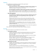
1 2 3 4 In In In In the the the the case case case case of of of of an an an an XP20000 XP20000 XP20000 XP20000 Disk Disk Disk Disk Array, Array, Array, Array, the the the the name name name name of of of of the the the the package package package package location location location location is is is is 1G. 1B. 1H. 1A.
Table 10 SAID Values for the PATH LINK Parameter (REAR CL2) (continued) Package Location 1 2 3 4 Port SAID Package Location Port CL6-H X'0057' CL6-R CL8-H X'0077' CL8-R SAID Package Location Port SAID Package Location Port SAID X'005F' CLE-M X'00DB' CLE-D X'00D3' X'007F' CLG-M X'00FB' CLG-D X'00F3' In the case of an XP20000 Disk Array, the name of the package location is 2L. n the case of an XP20000 Disk Array, the name of the package location is 2E.
3 Preparing for Universal Replicator for Mainframe Operations This chapter describes Universal Replicator for Mainframe operations involving the XP primary and secondary storage systems, the remote copy connections between the primary/secondary storage systems, and the host(s) at the primary and secondary sites, as well as the licensed Universal Replicator for Mainframe remote console software.
NOTE: Universal Replicator for Mainframe can coexist with HP StorageWorks XP Continuous Access Journal in the same storage system. • • Remote copy connections − Fibre Channel (see “Setting up Remote Copy Connections” (page 62)): ◦ Multimode or single-mode optical fibre cables are required at both the primary storage system and secondary storage system. ◦ For distances up to 0.5 km, multimode optical shortwave fiber cables are required between the primary storage system and secondary storage system.
Figure 9 z/Linux Use: Configuration Example of the Case When the Consistency is not Maintained Contact your HP support representative for the latest information on platform support for Universal Replicator for Mainframe and when you use z/Linux as the host OS. • A computer that runs Remote Web Console (Remote Web Console computer): The Remote Web Console software is required for XP disk array Universal Replicator for Mainframe operations.
NOTE: Administrator or Universal Replicator for Mainframe write access to the Remote Web Console Java applet program is required to perform Universal Replicator for Mainframe operations. Users without Administrator or Universal Replicator for Mainframe write access can only view Universal Replicator for Mainframe information.
NOTE: Universal Replicator for Mainframe does not support operations in which one primary data volume is copied to more than one secondary data volume, or more than one primary data volume is copied to one secondary data volume. Because Universal Replicator for Mainframe operates on volumes rather than on files, multivolume files require special attention.
NOTE: • The CU emulation type 3990-6, 3990-6E, 2105, or 2107 is required for SMS I/O time stamping of Universal Replicator for Mainframe journals. If one of these CU emulation types is used, volumes with the 3380 emulation type must not be used. • The CU emulation type H-65A2 is used for the HITAC M series and supports all types of M series volumes. Table 12 (page 53) lists the volumes and the volume capacity that can be used for the Universal Replicator for Mainframe data volume and journal volume.
Table 12 Supported Data Volume and Journal Volume (continued) Type Support specifications Data Volume Maximum volume capacity 3380-3 2.377 GB 3380-E 1.26 GB 3380-J 0.63 GB 3380-K 1.890 GB 3390-1 0.964 GB 3390-2 1.892 GB 3390-3 2.838 GB Journal Volume 3390-3R 3390-9 8.510 GB 3390-L 27.80 GB 3390-M 55.60 GB OPEN-V OPEN-V volumes cannot be used as data volumes. Capacity of OPEN-V volumes can be determined freely, depending on the VLL volume specifications. The minimum capacity is 48.
with custom-size emulation types as well as standard-size emulation types. When custom-size emulation types are assigned to Universal Replicator for Mainframe pairs, the secondary data volume must have the same capacity as the primary data volume. The Universal Replicator for Mainframe remote console software displays the emulation type of the primary data volumes and secondary data volumes.
Table 16 Number of Cylinders According to Each Emulation Type (continued) Emulation type • Number of Cylinders 3390-9 10,017 3390-L 32,760 3390-M 65,520 H6586-G 1,770 H6586-J 885 H6586-K 2,655 H6588-1 1,113 H6588-3 3,436 H6588-9 10,017 H6588-L 32,760 NF80-E 1,770 NF80-J 885 NF80-K 2,655 The number of the required bitmap areas: The number of bitmap areas to be used by all data volumes that form pairs is calculated from the number of cylinders.
Table 17 Relationship between Additional Shared Memory and Total Number of Bitmap Areas of the Storage System (continued) Additional Shared Memory for Universal Replicator for Mainframe Total Number of Bitmap Areas of Storage System Extension 2 32,768 Extension 3 (available only for an XP24000 Disk Array) 44,256 Extension 4 (available only for an XP24000 Disk Array) 65,536 Use the following formula to calculate the maximum possible number of pairs that can be created, based on the number of bitmap a
Table 18 Maximum Number of Pairs According to Each Emulation Type, When Pairs Are Created Without the Use of a VLL Volume (continued) Emulation Type Maximum number of pairs Additional shared memory for Universal Replicator for Mainframe is installed 58 Extension 1 Extension 2 Extension 3 Extension 4 H6588-3 7,424 16,384 32,768 32,768 32,768 H6588-9 3,712 8,192 16,384 22,128 32,768 H6588-L 1,484 3,276 6,553 8,851 13,107 NF80-E 7,424 16,384 32,768 32,768 32,768 NF80-J 7,424 16
IMPORTANT: The bitmap areas that are used for Universal Replicator for Mainframe are also used for XP Continuous Access Journal, TrueCopy for Mainframe, and XP Continuous Access. If you use Universal Replicator for Mainframe with XP Continuous Access Journal, TrueCopy for Mainframe, and XP Continuous Access, use the total number of each pairs to calculate the maximum number of pairs.
of the journal group is applied to the data volume pair. For 3DC configurations, see “TrueCopy for Mainframe Synchronous (3DC Cascading Configuration)” (page 82). • Table 20 (page 60) shows the specifications of the relationship between the data volumes, between the journal volumes, and between the data volumes and journal volumes in a journal group. Table 20 Journal Group Volume Specifications Item Support specifications Emulation type Same emulation type.
Universal Replicator for Mainframe does not allow the secondary data volume to be online (except while the pair is split). If the secondary data volume is online, the Universal Replicator for Mainframe add pair operation will fail.
Setting up Remote Copy Connections The following figure shows the remote copy connection configurations for Universal Replicator for Mainframe operations. The primary storage system and secondary storage system of each Universal Replicator for Mainframe pair must be connected via optical fiber cables. If you use multimode shortwave optical fiber cables, fibre cables up to 1.5 km in length and up to two switches are required for distances greater than 0.5 km.
Figure 11 Direct Remote Copy Connections *To set ports, use LUN Manager and set port topology to: Fabric off, FC-AL.
Figure 13 Extender Remote Copy Connection CAUTION: When an MCU and RCU are connected via switches with channel extender and multiple remote copy paths are assembled, the capacity of data to be transmitted may concentrate on particular switches, depending on the configuration and the settings of the switch routing. Enabling the Universal Replicator for Mainframe Option(s) To operate the Universal Replicator for Mainframe software, a computer for Remote Web Console is required.
Figure 14 Using More than One Primary and Secondary Storage System for Remote Copy When primary hosts write data to primary data volumes, the hosts add a time stamp to the data. Secondary storage systems check the time stamps and then restore data to data volumes in chronological order (older data is restored earlier), so that the data update sequence is maintained. For details about the time-stamping function, see “Host I/O Time Stamp” (page 25).
Basic Behavior When Using Multiple Primary and Secondary Storage Systems This section explains the basic behavior of Universal Replicator for Mainframe under the following conditions: • There are two primary storage systems and two secondary storage systems. • The status of all the Universal Replicator for Mainframe pairs that use journal groups in the extended consistency group is Duplex. For details on extended consistency groups, see “Extended Consistency Groups” (page 22).
The flow of the arbitration processing is as follows: 1. 2. 3. 4. From journal data in restore journal groups registered in the extended consistency group, the supervisor DKC collects the time stamps of journal data that has not been restored. The supervisor DKC compares the time stamps, and then selects the oldest time stamp. The supervisor DKC requests the subordinate DKCs to restore the journal data that has the selected time stamp.
Figure 16 An Example of Connections Among Secondary Storage Systems Based on the example in Figure 16 (page 68), the following subsections explain configuration of paths and ports, and creation of remote command devices. Configuring Paths and Ports to Establish Connections among Secondary Storage Systems To establish connections among secondary storage systems, you must configure external ports on the storage system that should be used as the supervisor DKC.
The emulation type of command devices and remote command devices must be OPEN-V. For details on remote command devices, see the HP StorageWorks XP24000/XP20000 External Storage Software User's Guide. CAUTION: Performing maintenance operations on remote command devices (for example, devices A and B in Figure 16 (page 68)) used for connections between secondary storage systems will cause the pairs to be suspended as if there was a failure.
Table 21 Whether Non-Universal Replicator for Mainframe Volumes Can Be Used as Universal Replicator for Mainframe Volumes (continued) Functions and Volumes Can the Volumes be Used as Primary Data Volumes? Can the Volumes be Used as Secondary Data Volumes? Can the Volumes be Used as Journal Volumes? XP Auto LUN Software 2 Source volume Yes Yes No (when volume migration is in progress) Note that volume migration stops when the source volume is used as a primary data volume.
Table 21 Whether Non-Universal Replicator for Mainframe Volumes Can Be Used as Universal Replicator for Mainframe Volumes (continued) Functions and Volumes Volume registered in a security group Can the Volumes be Used as Primary Data Volumes? Yes Can the Volumes be Used as Secondary Data Volumes? Yes Can the Volumes be Used as Journal Volumes? No However, if the volume is disabled for use as an S-VOL, the volume cannot be used as a secondary data volume.
and/or secondary sites. Table 22 (page 72) describes the host pair status reporting for Universal Replicator for Mainframe volumes, ShadowImage for Mainframe volumes, and Universal Replicator for Mainframe/ShadowImage for Mainframe shared volumes. Table 23 (page 72) shows the currency of the data on a shared Universal Replicator for Mainframe/ShadowImage for Mainframe volume based on the Universal Replicator for Mainframe and ShadowImage for Mainframe pair status.
Figure 17 (page 73) through “ShadowImage for Mainframe T-VOL in Split Status Functioning as a Universal Replicator for Mainframe Primary Data Volume” (page 75) show the various Universal Replicator for Mainframe/ShadowImage for Mainframe configurations which share volumes.
Figure 18 Shared Universal Replicator for Mainframe Secondary Data Volume and ShadowImage for Mainframe S-VOL CAUTION: If you use a Universal Replicator for Mainframe secondary data volume as a ShadowImage for Mainframe S-VOL as shown in Figure 18 (page 74), the write operation to the Universal Replicator for Mainframe primary data volume takes time.
Figure 19 Shared Universal Replicator for Mainframe Primary Data Volume and ShadowImage for Mainframe S-VOL and Universal Replicator for Mainframe Secondary Data Volume and ShadowImage for Mainframe S-VOL • Universal Replicator for Mainframe/ShadowImage for Mainframe configurations where a ShadowImage for Mainframe T-VOL in Split status is used as a Universal Replicator for Mainframe primary data volume In the following example, the ShadowImage for Mainframe T-VOL in Split status is also functioning as a
6. 7. 8. 9. Execute the Business Continuity Manager YKDELETE command on the ShadowImage for Mainframe pair to release the pair (see “Restoring a ShadowImage for Mainframe S-VOL - Step 6” (page 77)). Execute the Business Continuity Manager YKMAKE command on the ShadowImage for Mainframe pair to perform copying in the original direction (see Figure 21 (page 76)).
Figure 24 Restoring a ShadowImage for Mainframe S-VOL - Step 4 Figure 25 Restoring a ShadowImage for Mainframe S-VOL - Step 5 Figure 26 Restoring a ShadowImage for Mainframe S-VOL - Step 6 Figure 27 Restoring a ShadowImage for Mainframe S-VOL - Step 7 Interoperability with Other Products and Functions 77
Figure 28 Restoring a ShadowImage for Mainframe S-VOL - Step 8 Figure 29 Restoring a ShadowImage for Mainframe S-VOL - Step 9 Using the At-Time Split Function When Combining Universal Replicator for Mainframe with ShadowImage for Mainframe When a Universal Replicator for Mainframe secondary data volume (S-VOL) is specified as an S-VOL of a ShadowImage for Mainframe pair, you can specify the time for the backup copy operation for Universal Replicator for Mainframe by using the At-Time Split function of the
The At-Time Split function has the following restrictions when Universal Replicator for Mainframe and ShadowImage for Mainframe are used in conjunction: • The At-Time Split function can be executed by Business Continuity Manager, but cannot be executed by Remote Web Console. • You can execute split operations on ShadowImage for Mainframe pairs that belong to ShadowImage for Mainframe consistency groups. • You can apply one split operation to one ShadowImage for Mainframe consistency group.
4. that, split operations will be executed on ShadowImage for Mainframe pairs which are in conjunction with a Universal Replicator for Mainframe S-VOL. After ShadowImage for Mainframe has completed the split operations, Universal Replicator for Mainframe will resume the suspended restore operation of the restore journal.
Figure 31 Configuration of Multiple Journal Groups Registered in One ShadowImage for Mainframe Consistency Group If you use the At-Time Split function when combining Universal Replicator for Mainframe with ShadowImage for Mainframe, take the following considerations into account: • The specified split time is enabled even after the split operation has been executed on a ShadowImage for Mainframe pair.
ShadowImage for Mainframe consistency group, pairs can be deleted. If you delete the following pairs, the specified split time will be deleted: ◦ Delete all the ShadowImage for Mainframe pairs belonging to the ShadowImage for Mainframe consistency group. ◦ Delete all the Universal Replicator for Mainframe pairs belonging to the Universal Replicator for Mainframe restore journal group.
The utilization rate of the primary site in the 3DC cascading configuration rises compared with the configuration which consists of only data volume as well as the operation of TrueCopy for Mainframe Synchronous. Basic Behavior This section explains the basic behavior of a 3DC cascading configuration under the following conditions: • The status of the TrueCopy for Mainframe Synchronous pair is Duplex. The status of the Universal Replicator for Mainframe pair is also Duplex.
Hardware Configuration This section explains the hardware configuration for a 3DC cascading configuration using TrueCopy for Mainframe Synchronous and Universal Replicator for Mainframe. In a 3DC cascading configuration, three storage systems are required. It is recommended that Business Continuity Manager is installed on the hosts in the primary site, the intermediate site, and the secondary site. Remote Web Console computers are required for these sites.
4. Issue a request for creating a Universal Replicator for Mainframe pair to the MCU where Universal Replicator for Mainframe is installed. When creating a Universal Replicator for Mainframe pair, be sure to select a value from 1 to 3 as the mirror ID. 5. Wait until the status of the Universal Replicator for Mainframe pair becomes Duplex.
10. Use volumes in the primary site to resume your business tasks. 11. Execute the YKDELETE command onto journal groups that will make a Universal Replicator for Mainframe pair between the intermediate site and the secondary site. The system returns to the status before the 3DC cascading configuration was set up. For detailed information about Business Continuity Manager usage and copy statuses, see the HP StorageWorks Business Continuity Manager Software User's Guide.
Update sequence consistency will be maintained with the Universal Replicator for Mainframe secondary data volume.
Hardware Configuration A computer system in a 3DC multi-target configuration requires the following three sites: • Primary site for both TrueCopy for Mainframe Synchronous and Universal Replicator for Mainframe • Secondary site for TrueCopy for Mainframe Synchronous • Secondary site for Universal Replicator for Mainframe Each of these sites requires one storage system and Remote Web Console computers.
◦ The storage system must have a Universal Replicator for Mainframe master journal volume. ◦ If you use Business Continuity Manager, you need to make settings on the storage system. See the HP StorageWorks Business Continuity Manager Software User's Guide for information about settings required for volume operations in remote sites.
For detailed information about installing and using TrueCopy for Mainframe Synchronous, see the Hitachi TrueCopy™ for Mainframe User's Guide: HP XP24000 Disk Array, HP XP20000 Disk Array. For detailed information about Universal Replicator for Mainframe journal group configuration, see “Journal Group Operations” (page 27). For detailed information about port configuration, see “Configuring Port Attributes” (page 144).
differential data between the primary and secondary data volumes may be stored in the master journal group. Particularly in the following cases, the delta resync operation is not performed because the necessary journal data does not exist: • When, after creating the Universal Replicator for Mainframe pair, the primary data volume in the Universal Replicator for Mainframe pair for the delta resync operation is updated.
Figure 35 Configuration of the Delta Resync Operation to Support Remote Command Devices To create the above configuration, perform following operations: 1. 2. 3. 4. Configure paths between external ports and target ports. For detail about the external ports, see the HP StorageWorks XP24000/XP20000 External Storage Software User's Guide. For instruction on setting paths, see the HP StorageWorks XP24000/XP20000 LUN Manager User's Guide. Create command devices in all sites.
configuration after removing failures from the primary site and other locations. The resulting 3DC multi-target system uses the former TrueCopy for Mainframe secondary volume as a primary volume. To change the system into a 3DC multi-target configuration: 1. 2. Use Business Continuity Manager to execute the YKDELETE command (a command for releasing a pair) on the journal group corresponding to the former Universal Replicator for Mainframe pair.
Figure 37 Transferring Business Tasks from the TrueCopy for Mainframe Secondary Site to the Primary Site (in a 3DC Cascading Configuration) Transferring Business Tasks from the TrueCopy for Mainframe Secondary Site to the Primary Site (in a 3DC Multi-target Configuration) If you remove failures from the primary site and other locations and then the system is changed to a 3DC multi-target configuration, you can transfer your business tasks back to the primary site.
Figure 38 Transferring Business Tasks from the TrueCopy for Mainframe Secondary Site to the Primary Site (in a 3DC Multi-target Configuration) Transferring Business Tasks from TrueCopy for Mainframe Secondary Site to the Primary Site (When the Delta Resync Operation is Performed in 3DC Multi-target Configuration) If you remove the failures from the primary site and other locations, and then the system is changed to 3DC multi-target configuration, you can transfer your business tasks back to the primary sit
Table 24 Changes of Universal Replicator for Mainframe Pair Status by the Delta Resync Operation (When Business Tasks are Transferred from TrueCopy for Mainframe Secondary Site to the Primary Site) Universal Replicator for Mainframe Pair Pair Status before the Delta Pair Status after the Delta Resync Operation Resync Operation Primary Data Secondary Primary Data Volume Data Volume Volume Secondary Data Volume Universal Replicator Hold for Mainframe pair between TrueCopy for Mainframe Synchronous primary
Table 25 Pair Status and Operation after Recovery of the Primary Site Invalid Pair Status Perform this operation before transferring business tasks back to the Primary Site Primary site: Pending Duplex 1. Make sure that the status of the pair in the primary site is Suspend. 2. Release the Universal Replicator for Mainframe pair from the Universal Replicator for primary site. Mainframe secondary site: Hold 3. Make sure that all the pairs belonging to the journal group in the primary site are released. 4.
Figure 39 Transferring Business Tasks from the TrueCopy for Mainframe Secondary Site to the Primary Site (When the Delta Resync Operation is Performed in 3DC Multi-target Configuration) Recovering from Failures in the Primary Site and the TrueCopy for Mainframe Synchronous Secondary Site If a disaster or failure occurs in both the primary site and the TrueCopy for Mainframe Synchronous secondary site in a 3DC multi-target configuration, you can resume your business tasks by using the secondary volume in th
Figure 40 Recovering from Failures in the Primary Site and the TrueCopy for Mainframe Synchronous Secondary Site Transferring Business Tasks from the Universal Replicator for Mainframe Secondary Site to the Primary Site If you follow the instructions in the previous section and then remove failures from the primary site and the TrueCopy for Mainframe Synchronous secondary site, you can transfer your business tasks back to the primary site.
Figure 41 Transferring Business Tasks from the Universal Replicator for Mainframe Secondary Site to the Primary Site XP Auto LUN Except when the pair status is Pending or Duplex, you can specify the Universal Replicator for Mainframe primary or secondary volumes as the source volumes of XP Auto LUN. On the contrary, you cannot specify Universal Replicator for Mainframe data volumes and journal volumes as the target volumes of XP Auto LUN.
Universal Replicator for Mainframe Copy Operations • The data which is copied to the Universal Replicator for Mainframe P-VOL by Compatible Flash Copy V2 is asynchronously copied with the initial copy operation to the Universal Replicator for Mainframe S-VOL. Based on the speed of the initial copy processing to Universal Replicator for Mainframe S-VOL, the concordance rate of the Universal Replicator for Mainframe pair is calculated.
• The data which is copied to the TrueCopy for Mainframe M-VOL or Universal Replicator for Mainframe P-VOL by Compatible Flash Copy V2 is asynchronously copied with the initial copy operation to the TrueCopy for Mainframe R-VOL or Universal Replicator for Mainframe S-VOL. Based on the speed of the data copy to TrueCopy for Mainframe R-VOL or Universal Replicator for Mainframe S-VOL, the concordance rate of the TrueCopy for Mainframe pair and Universal Replicator for Mainframe pair is calculated.
primary storage system goes through two phases; in one phase the data transfer speed remains almost unchanged, and in another phase the data transfer speed increases temporarily.
Computing the Journal Volume Capacity In the following figure, the size of the shaded area indicates the amount of journal data to be stored in journal volumes as a result of a temporary increase in data transferred. If a temporary communication path failure occurs between the primary storage system and the secondary storage system, journal transfers between the primary storage system and the secondary storage system will stop temporarily.
Planning the Data Transfer Speed before Reversing Data Volumes When a failure occurs at a host, one of the failure recovery measures is to reverse the primary data volume and the secondary data volume (that is, change the copy direction). To reverse the primary data volume and the secondary data volume, usually you must ensure that the data transfer speed is the same before and after you reverse these data volumes.
exceeds the data transfer speed in the normal status mentioned earlier. The maximum number of paths for each pair of the primary DKC and the secondary DKC is 8. Configuration where XP12000/XP10000 and XP24000/XP20000 Disk Arrays are Connected Universal Replicator for Mainframe can execute remote copy operations in a system configuration where XP24000/XP20000 and XP12000/XP10000 Disk Arrays are connected. Specifically, the following configurations are supported.
NOTE: • There is only one LDKC: LDKC00. • The steps to configure a logical path between an XP24000/XP20000 Disk Array and an XP12000/XP10000 Disk Array is the same as the steps to set logical paths between volumes of an XP24000/XP20000 Disk Array. For detailed information about the steps to configure logical paths, see “Configuring Storage Systems and Logical Paths” (page 142).
multi-target configuration, see “TrueCopy for Mainframe Synchronous (3DC Multi-target Configuration)” (page 86)). Connection with an XP12000/XP10000 Disk Array When Using Extended Consistency Groups Universal Replicator for Mainframe can perform remote copy operations from more than one primary storage system to more than one secondary storage system using extended consistency groups. Primary storage systems can be a mixture of XP24000/XP20000 Disk Arrays and XP12000/XP10000 Disk Arrays.
Figure 46 Examples of Configurations where an XP12000 Disk Array is Used as the Subordinate DKC ◦ When the supervisor DKC is an XP12000/XP10000 Disk Array and the subordinate DKCs are XP24000/XP20000 Disk Arrays. When the supervisor DKC of the secondary storage system is an XP12000/XP10000 Disk Array and the subordinate DKCs are XP24000/XP20000 Disk Arrays, there are limitations for the journal groups that can be registered in the extended consistency group.
NOTE: Journal groups of LDKCs other than LDKC00 cannot be registered in the extended consistency groups when the supervisor DKC is an XP12000/XP10000 Disk Array, even if the number of LDKCs is expanded in a future version.
4 Using the Universal Replicator for Mainframe GUI This chapter describes how to use the Universal Replicator for Mainframe graphical user interface: • “Journal Operation Window” (page 111) • “Pair Operation Window” (page 115) • “DKC Operation Window” (page 121) • “Usage Monitor Window” (page 126) • “History Window” (page 127) • “Optional Operation Window” (page 131) • “EXCTG Operation Window” (page 133) Journal Operation Window To configure journal groups, use the Journal Operation window of
CAUTION: You cannot perform the following operations on journal groups numbered 10 to FF. • Registering journal volumes in journal groups • Deleting journal volumes from journal groups • Changing journal group options • Restoring mirrors Table 26 Journal Operation Window Details – Tree Item Tree Description Lists journal groups in the local storage system, which is the storage system you are logged in.
Table 27 Journal Operation Window Details – List Item Journal Operation list Description If a master journal group or a restore journal group is selected in the tree, the Journal Operation list shows a list of mirrors. A mirror is a combination of a master journal group and a restore journal group. One row in this list represents one mirror (or one journal group). If another journal group is selected in the tree, the Journal Operation list shows information about the selected journal group.
Table 27 Journal Operation Window Details – List (continued) Item Description Hold: A Universal Replicator for Mainframe pair for the delta resync operation is created. : An error occurred with the Universal Replicator for Mainframe pair for the delta resync operation. Holding: A Universal Replicator for Mainframe pair for delta resync operation is being created. Hold (Failure) Blank: No data volumes are registered in this journal group. • Mirror ID: Identifies the mirror.
Table 28 Journal Operation Window Details – Other Item Preview list Description The Preview list shows changes that have been made in the window. Changes appear in the Preview list before they are applied to the storage systems. If you are sure that the information in the Preview is correct, click Apply to send the changes to the storage system.
To open the Pair Operation window, do either of the following: • If Universal Replicator for Mainframe has not been started: ◦ Select Go, Universal Replicator for Mainframe and then Pair Operation on the menu bar of the Remote Web Console main window. Universal Replicator for Mainframe starts and the Pair Operation window is displayed. • If Universal Replicator for Mainframe has already been started: ◦ Select the Pair Operation tab. The Pair Operation window opens.
remaining volume pairs in the list. The Previous button displays the previous 1,024 volume pairs in the list. ◦ • Next: The list can display up to 1,024 volume pairs simultaneously. If the number of volume pairs exceeds 1,024, you can use the Previous and Next buttons to display the remaining volume pairs in the list. The Next button displays the next 1,024 volume pairs in the list. List: Displays volumes in the local storage system. One row represents one volume.
is blank if the volume in the local storage system is neither a primary data volume nor a secondary data volume. • S/N(LDKC) : The serial number of the remote storage system. This column is blank if the volume in the local storage system is neither a primary data volume nor a secondary data volume. The column can be blank while the pair is in transition to the Simplex status. To view the latest information in this column, refresh the screen.
the synchronization rate (that is, concordance rate) is 100 percent if the contents of the secondary data volume are the same before and after the volume pair became split. CAUTION: If a failure in the initial copy operation causes the volume pair to be split, this column displays nothing. If a failure occurs in the initial copy operation, the Detailed Information window (“Detailed Information Window” (page 198)) shows the message Initial copy failed. In the following cases, this column will be blank.
Duplex: The volume is paired with another volume. The two volumes are fully synchronized. All updates from the host to the primary data volume are duplicated at the secondary data volume. Suspend: The pair has been split. The primary data volume and the secondary data volume are not synchronized. Suspending: The primary data volume and the secondary data volume are not synchronized. This pair is in transition from the Pending or Duplex status to the Suspend status.
Table 29 Pair Operation Window Details (continued) Item Operation Description The operation that will occur when you click Apply. • Add Pair: Create pairs • Suspend Pair: Split pairs • Resume Pair: Restore pairs • Delete Pair: Release pairs • Change Pair Option: Change pair option(s) • Blank: Nothing will occur when you click Apply. Preview The number to the left of the slash (/) indicates the number of items displayed in the Preview list.
To open the DKC Operation window, do either of the following: • If Universal Replicator for Mainframe has not been started: ◦ Click Go, Universal Replicator for Mainframe and then DKC Operation on the menu bar of the Remote Web Console main window. Universal Replicator for Mainframe starts and the DKC Operation window is displayed. • If Universal Replicator for Mainframe has already been started: ◦ Select the DKC Operation tab. The DKC Operation window opens.
Table 30 DKC Operation Window Details Item Display Description Changes information in the DKC Operation window. • DKC shows information about the remote storage systems and the logical paths. Port shows information about the ports on the local storage system.
Figure 52 DKC Operation Window Item Description Lists the remote storage systems at each LDKC in the local storage systems. The following information appears to the right of the icon of the remote storage system: Tree • Controller ID of a remote storage system (the model name of the remote storage system) • Serial number of the remote storage system • Path group ID The LDKC#01 cannot be used in this version.
Figure 53 Logical Paths Information in the DKC Operation Window Table 31 Logical Paths Information in the DKC Operation Window Item Path Gr. ID Description The path group ID. The icon indicates the status of the path: The logical path is in normal status. A failure occurred to the logical path. M-R Path The channel type of the logical paths between the local storage system and the remote storage system. This column always displays Fibre. Status Indicates whether the logical path is in normal status.
Figure 54 Port Information in the DKC Operation Window Table 32 Port Information in the DKC Operation Window Item Tree Description The channel adapters and ports on the local storage system. The following information appears to the right of the icon: Channel adapter (Fibre Channel interface) Target port Initiator port External port Port in initiator/external mix mode Operation List The ports on the local storage system: • Port: Port number.
To open the Usage Monitor window, do either of the following: • If Universal Replicator for Mainframe has not been started: ◦ Select Go, Universal Replicator for Mainframe and then Usage Monitor on the menu bar of the Remote Web Console main window. Universal Replicator for Mainframe starts and the Usage Monitor window is displayed. • If Universal Replicator for Mainframe has already been started: ◦ Select the Usage Monitor tab. The Usage Monitor window is displayed.
To open the History window, do either of the following: • If Universal Replicator for Mainframe has not been started: 1. Select Go, Universal Replicator for Mainframe and then History on the menu bar of the Remote Web Console main window. Universal Replicator for Mainframe starts and the History window opens. The History window may not show latest operation history. To view the latest operation history, go to the next step. 2. Click File, Refresh on the menu bar of the Remote Web Console main window.
Table 34 History Window Details (continued) Item Description Page The number of the current page and the total number of pages. The display format of Page is the number of current page / total number of pages. If there is no history file, nothing is appears. Export Saves operation history in a CSV file. You cannot save the history file during operation history update. Save operation history in a text file after operation history is updated.
Table 35 Operations Displayed in the History Window (continued) Displays Descriptions Status Change by MCU(Simplex to Pending) The status of the data volume pair was changed from Simplex to Pending because of an operation from the primary storage system. Status Change by MCU(Simplex to Duplex) The status of the data volume pair was changed from Simplex to Duplex because of an operation from the primary storage system.
Table 35 Operations Displayed in the History Window (continued) Displays Descriptions Status Change by RCU(Hold to Simplex; Delete Pair Start) An operation for releasing a pair has been started at the secondary storage system. The status of the data volume pair will change from Hold to Simplex. Status Change to Hold The status of the secondary data volume was changed to Hold because of a delta resync operation. Unknown The storage system could not identify the type of operation.
To open the Optional Operation window, do either of the following: • If Universal Replicator for Mainframe has not been started: ◦ Select Go, Universal Replicator for Mainframe and then Optional Operation on the menu bar of the Remote Web Console main window. Universal Replicator for Mainframe starts and the Optional Operation window is shown. • If Universal Replicator for Mainframe has already been started: ◦ Select the Optional Operation tab to open the Optional Operation window.
NOTE: Information on the Optional Operation window will be updated when you do one of the following: • Click Apply. • Select another tab and then reselect the Optional Operation tab. • Click File, Refresh on the menu bar of the Remote Web Console main window. • Select Modify mode when you are in View mode. EXCTG Operation Window To make settings on extended consistency groups, use the EXCTG Operation window.
To open the EXCTG Operation window, do either of the following: • If Universal Replicator for Mainframe has not been started: ◦ Select Go, Universal Replicator for Mainframe and then EXCTG Operation on the menu bar of the Remote Web Console main window. Universal Replicator for Mainframe starts and the EXCTG Operation window appears.
• Select the EXCTG Operation tab. The EXCTG Operation window appears.
Using the Universal Replicator for Mainframe GUI
Table 37 EXCTG Operation Window Details Item Tree Description Lists extended consistency groups. See Figure 59 (page 135) for details. ◦ Registered: When selected, the upper-right list shows extended consistency groups in which journal groups are registered. Double-clicking this item shows LDKCs. Selecting an LDKC shows information about the extended consistency groups belonging to the LDKC. Double-clicking the LDKC shows extended consistency groups in which journal groups are registered.
NOTE: Information on the EXCTG Operation window is updated when you do one of the following: • Click Apply. • Select another tab and then reselect the EXCTG Operation tab. • Click File, Refresh on the menu bar of the Remote Web Console main window. • Select Modify mode when you are in View mode. Displaying a List of Extended Consistency Groups The EXCTG Operation window allows you to view a list of extended consistency groups. To view a list of extended consistency groups: 1. 2.
Item C/T Description The consistency time of an extended consistency group. For example, if the consistency time is 10:00 a.m., secondary data volumes in the extended consistency group are synchronized with the primary data volumes that were available as of 10:00 a.m. The consistency time is displayed in the following format: month/date/year hour/minute/second For the number of seconds, the number before and after the decimal point appears.
1. 2. 3. Display the EXCTG Operation window. Double-click Registered and then an LDKC from those listed below Registered in the tree. Select an extended consistency group that is displayed in the tree. The list shows a list of storage systems registered in the extended consistency groups: Figure 61 Storage Systems in the EXCTG Operation Window Item Description S/N(LDKC) Serial number of a storage system and LDKC number enclosed in parentheses.
Item Attribute Description The attribute of a journal group. A master journal group A restore journal group Status Status of a journal group If a journal group is in Active status and you want to know whether any data volume pair in this journal group is split, you must log in to the storage system containing the journal group, and then display the Journal Operation window to check the status of the journal group.
5 Configuring Storage Systems and Logical Paths This chapter explains how to configure storage systems and logical paths for Universal Replicator for Mainframe in your system: • “Reviewing Storage System and Logical Paths” (page 142) • “Configuring Port Attributes” (page 144) • “Configuring Storage System Options” (page 146) • “Establishing the Relationship between Primary and Secondary Storage Systems (Add DKC)” (page 147) • “Changing Options for Logical Paths and Storage Systems” (page 150) • “
• Delete logical paths • Display status of logical paths • Delete the relationship between the primary and the secondary storage systems NOTE: • Throughout this chapter, the primary and the secondary storage systems are sometimes referred to as local storage systems or remote storage systems.
8. Register the primary and secondary data volumes and the journal groups that are paired from the Add Pair window in Pair Operation. NOTE: Universal Replicator for Mainframe pairs can only be registered by the primary storage system. 9. Exit the Universal Replicator for Mainframe remote console software, and disconnect from the storage system. Operate at a primary storage system and a secondary storage system. 10.
the storage system. Target ports must be configured on primary storage systems for Universal Replicator for Mainframe operations. • Initiator: An initiator port is a Fibre Channel port that sends commands to a remote storage system. Initiator ports must be configured on both primary and remote storage systems for Universal Replicator for Mainframe operations. • RCU target: An initiator port is a Fibre Channel port that receives commands from a remote storage system.
4. 5. 6. Do either of the following: • Select a channel adapter from the tree. • Select a port attribute (that is, target, RCU target or initiator) from the tree. Select and right-click the port that you want to configure. From the pop-up menu, select the desired port type (that is, initiator, RCU target, or target). The right-most column of the list displays Modified to indicate that you are modifying the attribute of the port.
NOTE: If an error occurs, the right-most column of the Preview list displays the error code. To view detailed information about the error, right-click the error code and then select Error Detail. An error message appears and gives you detailed information about the error. Figure 63 Storage System Option Settings in the Optional Operation Window • Activities: The number of volumes that can be copied concurrently during the initial copy and resynchronization operations.
One primary storage system can be associated with up to 64 secondary storage systems. Up to eight logical paths can be configured between one primary storage system and one secondary storage system. Therefore, one primary storage system can have up to 512 logical paths to secondary storage systems.
12. See the Preview list to check the settings that you have made. • To modify a setting, select and right-click the setting from the Preview list and then select Modify. A window appears and allows you to modify the setting. • To cancel a setting, select and right-click the setting in the Preview list and then select Cancel. 13. Click Apply to apply the settings that you have made. NOTE: If an error occurs, the right-most column of the Preview list displays the error code.
• Path Gr. ID: allows you to enter the path group ID. Path group IDs are used for identifying groups of logical paths. One path group can contain up to eight logical paths. Path group IDs are within the range of 1-FF (hexadecimal). If you select the Default check box, the default path group ID will be set. NOTE: In the current version, you cannot enter path group IDs. Also, you cannot clear the Default check box. The number of path group IDs per one remote storage system is always 1.
9. See the Preview list to check the settings that you have made. • To modify a setting, select and right-click the setting from the Preview list and then select Modify. A window appears and allows you to modify the setting. • To cancel a setting, select and right-click the setting in the Preview list and then select Cancel. 10. Click Apply to apply the settings that you have made. NOTE: If an error occurs, the right-most column of the Preview list displays the error code.
1. 2. Make sure the remote copy connections are properly configured. Ensure that the Remote Web Console main window is in Modify mode. For detailed information about how to do this, see the HP StorageWorks XP24000/XP20000 Remote Web Console User's Guide. 3. 4. 5. 6. Ensure that the DKC Operation window is displayed. In Display, select DKC. Do either of the following: • In the tree, select a remote storage system.
NOTE: When specifying a port, you can use the keyboard to enter the port number. When you enter the port number, you can abbreviate the port number to two characters. For example, you can enter 1A instead of CL1-A. You can use uppercase and lowercase letters. • Pair-Port: Allows you to select an RCU target port on the remote storage system. NOTE: When specifying a port, you can use the keyboard to enter the port number. When you enter the port number, you can abbreviate the port number to two characters.
Figure 68 DKC Status Window The DKC Status window displays the following settings: • List: ◦ No.: displays serial numbers used for rows in the list ◦ Path Status: indicates status of a logical path (for details, see Table 38 (page 155)) ◦ Port: indicates a port on the local storage system ◦ Pair-Port: indicates a port on the remote storage system. • S/N: Indicates the serial number and LDKC number of the remote storage system.
Table 38 Logical Path Status Status Remarks Normal This path has been successfully established and can be used for Universal Replicator for Mainframe remote copy activities. Nothing An operation for configuring or deleting this logical path is in progress. Initialization Failed An error occurred with the initialization of a connection between the local and the remote storage system. The probable causes are: • No cable is connected to the local storage system.
4. 5. 6. Do either of the following: • In the tree, select a remote storage system. • In the list, select and right-click a remote storage system and then select Edit Path(s) from the pop-up menu. The list displays information about logical paths. In the list, select the logical path(s) that you want to delete. Right-click the list and then select Delete Path from the pop-up menu. A confirmation message appears. 7. 8. 9. Select OK to close the message.
NOTE: When you right-click the Preview list, you will find a command named Modify. This command is grayed out and, therefore, cannot be used. 6. Click Apply to apply the changes. NOTE: If an error occurs, the right-most column of the Preview list displays the error code. To view detailed information about the error, right-click the error code and then select Error Detail. An error message appears and gives you detailed information about the error.
Managing Power for Storage Systems and Network Relay Devices This section explains power management for storage systems and network relay devices during remote copy operations. In particular, this section discusses the following situations: • What happens when power is removed from storage systems or network relay devices due to some unexpected reason (see the next section).
primary storage systems. When powering off the primary storage systems, you must power off the supervisor DKC first, and then the subordinate DKCs. If the delta resync function to support the remote command devices is used, the SIM (SIM reference code = EFD0) to suggest that the device connected to the external storage system has been blocked is reported to the destination storage systems because the command devices are blocked due to the power-off of the storage system.
1. Power on the secondary storage system. If more than one secondary storage system is to be used with extended consistency groups, power on the subordinate DKCs first, and then the supervisor DKC. 2. If the secondary storage system is ready to resume remote copy operations, restore the data volume pairs that have been split, and then confirm that the status of the data volume pairs is Pending orDuplex. This operation must be performed at the primary site.
NOTE: After you turned the power on or off at both the primary and secondary storage system at the same time, if the status of a data volume pair of the primary storage system is Suspend and the status of a data volume pair of the secondary storage system is Duplex, you must suspend the data volume pair of the secondary storage system by using Remote Web Console.
6 Configuring Journal Groups This chapter describes the introduction of the Universal Replicator for Mainframe in your system and explains how to configure your system for remote copy operations: • “Reviewing Administrator Tasks for Managing Journals” (page 162) • “Registering Journal Volumes in a Journal Group” (page 163) • “Deleting Journal Volumes from a Journal Group” (page 168) • “Displaying Detailed Information about a Journal Group” (page 169) • “Changing Options for a Journal Group” (page 1
NOTE: Throughout this chapter, the primary and the secondary storage systems are sometimes referred to as local storage systems or remote storage systems. If you are logged into the primary storage system and are using Universal Replicator for Mainframe, the primary storage system is a local storage system and the secondary storage system is a remote storage system.
5. In the Free Volumes list of the Edit JNL Volumes window (“Edit JNL Volumes Window” (page 165)), select the volumes that you want to register. In the Free Volumes list, one row represents one volume. If you cannot find the volumes that you want to register, do any of the following: • Select the PG radio button, enter a parity group number in the text boxes to the right, and then select Show. The list displays volumes in the specified parity group. Finally, select the volumes that you want to register.
NOTE: If an error occurs, the right-most column of the Preview list displays the error code. To view detailed information about the error, right-click the error code and then select Error Detail. An error message appears and gives you detailed information about the error. Figure 70 Edit JNL Volumes Window The Edit JNL Volumes window displays the following: • JNL Volumes: Displays information about journal volumes. ◦ Parity Group: indicates the parity group where a journal volume belongs.
◦ CLPR: Indicates the number and the name of the CLPR where the journal volume belongs. ◦ Operation: Displays one of the following: Blank This column usually displays a blank. Add Indicates a volume to be added to a journal group Delete Indicates a volume to be deleted from a journal group • Add: Use this button when you register volumes in a journal groups. When registering volumes, you select the volumes from Free Volumes and then select Add to add the volumes to JNL Volumes.
• PG/CU change: The following radio buttons enable you to switch information in the Free Volumes list. ◦ PG: Use this radio button if you want the Free Volumes list to display volumes belonging to a parity group. If you select this radio button, specify a parity group number in the text boxes to the right, and then select the Show button, Free Volumes will display volumes in the specified parity group (see Figure 71 (page 167)). ◦ PG(Ext.
NOTE: ◦ You can specify the Timer Type option only when no journal volume is registered. If journal volumes are already registered, you cannot specify the Timer Type option. ◦ Ensure that the same timer type is specified in both the primary and the secondary sites. ◦ When you use Fujitsu OS, select Local in Timer Type. • JNL Group: Indicates the number of a journal group. • Current: Indicates the number and the capacity of journal volumes that currently exist in the journal group.
4. Do either of the following: • In the tree, right-click the selected journal group and then select JNL Volumes from the pop-up menu. • In the upper-right list, select and right-click the desired journal group and then select JNL Volumes from the pop-up menu. CAUTION: As a general rule, you can delete journal volumes only when the attribute of the journal group is Initial or when the status of the journal group is Stop or Hold(Failure).
3. 4. 5. Do either of the following: • In the tree, right-click the selected journal group and then select JNL Groups and JNL Status from the pop-up menu. • In the upper-right list, right-click the desired journal group and then select JNL Groups andJNL Status from the pop-up menu. In the JNL Group Detail window (Figure 73 (page 170)), view detailed information about the journal group. After you finish viewing the information, click Close to close the JNL Group Detail window.
• JNL Volumes: Indicates the number of journal volumes registered in the journal group. • JNL Capacity: Indicates the total capacity of all the registered journal volumes. The unit is cylinders for mainframe volumes. The unit is gigabytes for open-systems volumes. • Data Volumes: Indicates the number of data volumes associated with the journal group.
NOTE: When there is insufficient space in the cache, journal data will also be stored into the journal volume. ◦ Not Use: Journal data will not be stored into the cache. CAUTION: This setting does not take effect on master journal groups. However, if the Business Continuity Manager YKRESYNC REVERSE command is used to change a master journal group into a restore journal group, this setting will take effect on the journal group.
• ◦ Emulation: Indicates the emulation type of a journal volume. ◦ CLPR: Indicates the number and the name of the CLPR where the journal volume belongs. Mirrors: Displays a list of mirrors. If the remote command device is assigned to the mirror of TrueCopy for Mainframe Synchronous pair in 3DC multi-target configuration, and the mirror ID is 00, all columns other than mirror ID and remote command device are blank. ◦ Mirror ID: indicates a mirror ID.
3. Do either of the following: • In the tree, right-click a journal group from below Registered and then select JNL Groups and Change JNL Option from the pop-up menu. • In the upper-right list, right-click the desired journal group and then select JNL Groups and Change JNL Option from the pop-up menu. CAUTION: satisfied: You can select Change JNL Option only when one of the following conditions is • The attribute of the journal group is Initial. • The status of the journal group is Active.
NOTE: If an error occurs, the right-most column of the Preview list displays the error code. To view detailed information about the error, right-click the error code and then select Error Detail. An error message appears and gives you detailed information about the error.
• Copy Pace: Allows you to specify the pace (speed) for an initial copy activity for one volume. The default is Low. ◦ Low: The speed of the initial copy activity is slower than Medium and High. ◦ Medium: The speed of the initial copy activity is faster than Low and slower than High. To specify Medium, ensure that the amount of update I/Os (that is, write requests from hosts to primary data volumes) is 10 MB/s or less per one parity group.
is forwarded from the master journal group to the restore journal group, the two journal groups will have the same Path Watch Time value. ◦ Yes: The Path Watch Time value will be forwarded to the restore journal group. ◦ No: The Path Watch Time value will not be forwarded to the restore journal group. No is the default. ◦ Blank: The current setting of Forward Path Watch Time will remain unchanged. CAUTION: ◦ • This option cannot be specified in the secondary site.
NOTE: ◦ Ensure that the same timer type is specified in both the primary and the secondary sites. ◦ Do not change the Timer Type if At-Time Split function is used when Universal Replicator for Mainframe and ShadowImage for Mainframe are used in conjunction ◦ You can only specify System if the journal group belongs to an extended consistency group. ◦ When you use Fujitsu OS, select Local in Timer Type.
1. Ensure that the Remote Web Console main window is in Modify mode. For detailed information about how to do this, see the HP StorageWorks XP24000/XP20000 Remote Web Console User's Guide. 2. 3. Ensure that the Journal Operation window is displayed (see “Journal Operation Window” (page 111)). Do either of the following: • In the tree, select a master journal group or a restore journal group from below Registered.
This parameter takes effect only when the selected volume is a master journal group. • Range: Allows you to specify the split range. This parameter is always set to Group and cannot be changed. • Suspend Mode: Allows you to specify how to handle update data that are not reflected to the secondary data volume. The default is Flush. ◦ If you select Flush, update data will be reflected to the secondary data volume when you split the mirror.
7. 8. See the Preview list to check the mirrors that you want to restore. • To cancel restoring a mirror, select and right-click the mirror and then select Cancel. • If necessary, you can repeat steps 3 to 7 to specify other mirrors. Click Apply to restore the mirror(s). NOTE: If an error occurs, the right-most column of the Preview list displays the error code. To view detailed information about the error, right-click the error code and then select Error Detail.
assign the remote command device to the mirror of the journal group in the 3DC multi-target configuration. When the mirror status is Active, Halt, Stop, Hold, Holding, or Holding(failure), the remote command device can be assigned to the mirror. To assign a mirror to a remote command device, use the following procedure (this operation can be executed per journal group): 1. 2. 3. 4. 5. 6. 7. 8. 9. Ensure that the Remote Web Console main window is in Modify mode.
• Set: Applies the settings in the window to the Journal Operation window (see “Journal Operation Window” (page 111)). • Cancel: Cancels the settings and closes the dialog box. Releasing Assigned Remote Command Device To release a remote command device assigned to a mirror, use the following procedure (this operation can be executed per mirror): 1. 2. 3. 4. 5. 6. 7. Ensure that the Remote Web Console main window is in Modify mode.
7 Using Extended Consistency Groups This chapter explains how to perform remote copy operations between more than one primary and secondary storage system, as well as how to register journal groups in extended consistency groups (abbreviated as EXCTGs).
For details on reversing copy direction, see “Transferring Operations Back to the Primary Site” (page 227). • Configuring the secondary EXCTG: When you have more than one primary journal group (usually means more than one secondary journal group also), you must configure a secondary EXCTG in order for the secondary data volumes to be consistent across multiple journal groups.
12. Select ->Add. The selected journal groups move to the JNLG list on the right. NOTE: If the JNLG list on the right contains any journal group that you do not want to register, select the journal group from the list and then click <-Cancel. 13. From Mirror ID, select a mirror ID. NOTE: If a mirror ID is already specified and unchangeable, you do not need to select it. 14. If necessary, repeat steps 6 to 13. 15. Select Set to close the Add JNL Group window. 16.
NOTE: ◦ If JNLG of the local DKC is used in check box ON is selected, the serial number of the supervisor DKC is already specified and unchangeable. ◦ If JNLG of the local DKC is used in check box ON is cleared, you cannot specify the serial number of the supervisor DKC. ◦ You cannot set the same serial number to DKC-1 through DKC-4. • LDKC: Indicates the LDKC number of a storage system. • Controller ID: Indicates the controller ID of a storage system.
When you specify an extended consistency group and split data volume pairs in the specified group collectively, you can specify Flush or Purge as the suspend mode: • If you specify Flush, all pairs in the extended consistency group can be split while the consistency of the data update sequence will be maintained within that group. • If you specify Purge, the consistency of data update sequence will not be maintained within the extended consistency group.
NOTE: To cancel removal of a journal group, select and right-click the journal group and then select Cancel. 6. Click Apply to remove the journal group(s). NOTE: • • If an error occurs, the right-most column of the Preview list displays the error code. To view detailed information about the error, right-click the error code and then select Error Detail. An error message appears and gives you detailed information about the error.
Forcibly Removing Journal Groups from an Extended Consistency Group The Journal Operation window allows you to remove journal groups forcibly from an extended consistency group. CAUTION: To remove journal groups from an extended consistency group, you must first log in to the supervisor DKC and then follow the instructions in the previous section. Follow the procedure below only when you cannot remove the journal groups due to a communication failure between storage systems or some other reason.
8 Performing Pair Operations This chapter explains how to perform remote copy operations with Universal Replicator for Mainframe, including how to create pairs of a primary data volume and a secondary data volume: • “Filtering Information in the List in the Pair Operation Window” (page 191) • “Creating a Pair of Data Volumes” (page 193) • “Displaying Detailed Information about a Pair of Data Volumes” (page 198) • “Saving Pair Status Information into a Text File” (page 201) • “Changing Options for a
NOTE: • To restore the list to the default status (that is, the status before filtering), select Reset in the Display Filter window and then Set in the same window. • If you change settings in the Display Filter window, the changes will remain effective during the Universal Replicator for Mainframe session until you reset the settings. Figure 79 Display Filter Window The Display Filter window displays the following settings: • Host Group: Allows you to select the host group to be displayed.
• Sub Status: Allows you to specify the consistency status. The volume pairs in the specified status will be displayed in the list. For detailed information about the consistency status, see “Suspend Types” (page 41) and “Consistency Status for Suspended Universal Replicator for Mainframe Secondary Data Volumes” (page 43). • SEQCHK Only: Allows you to specify whether to display only the volume pairs in SEQCHK status.
7. In S-VOL, specify the secondary data volume. • Use the left drop-down list to specify a CU number. • Use the right drop-down list to specify an LDEV number. NOTE: If more than one primary data volume is specified in the list, you can specify secondary data volumes in three ways. For detailed information, see the explanation about the Select Other S-VOL(s) option later in this section. 8. 9.
Figure 80 Add Pair Window The Add Pair window displays the following settings: • P-VOL: Indicates a primary data volume. The numbers are the LDKC number, the CU number and the LDEV number of the primary data volume. NOTE: • ◦ P-VOL displays only one primary data volume even when two or more primary data volumes are selected in the Pair Operation window. P-VOL only displays the primary data volume that has the smallest volume number.
NOTE: • ◦ You can select only one secondary data volume even when two or more primary data volumes are selected in the Pair Operation window. Universal Replicator for Mainframe automatically specifies the other secondary data volumes. For detailed information, see the explanation about the Select Other S-VOL(s) option later in this section. ◦ If you selected more than one primary data volume, select the secondary data volume for the primary data volume being displayed.
NOTE: M-JNL and R-JNL do not display journal group numbers used by XP Continuous Access Journal. • DKC: Allows you to select the serial number (the LDKC number) and the controller ID (model name that indicates the model) of the secondary storage system. This option also allows you to specify the path type (that is, channel type). NOTE: The secondary storage system must be the same for all pairs being created during one operation.
• Set: Applies the settings to the Preview list in the Pair Operation window (“Pair Operation Window” (page 116)). • Cancel: Discards the settings. Displaying Detailed Information about a Pair of Data Volumes The Detailed Information window allows you to view detailed information about a pair of data volumes. To display detailed information about a pair of data volumes, follow the procedure below.
The Detailed Information window displays the following settings: • Status: Indicates the status of the pair. If the pair is split (or suspended), Status also displays the suspend type. If the pair is waiting for initial copy, Status also displays the word (Queuing). • Sync.: If the volume in the local storage system is a primary data volume, Sync. displays the progress of an initial copy operation. If the volume in the local storage system is a secondary data volume, Sync.
NOTE: ◦ If a volume is an external volume, the pound or gate symbol (#) appears after the LDEV number. For detailed information about external volumes, see the HP StorageWorks XP24000/XP20000 External Storage Software User's Guide. ◦ If a volume is a volume of an XP12000/XP10000 or XP24000/XP20000 Disk Array, 00 is displayed as the LDKC number. • CLPR: Indicates the CLPR number and the CLPR name of the volume in the local storage system. • M-JNL Group: Indicates the master journal group.
◦ Consistency Time: Indicates the time stamp transferred by the host computer if the secondary data volume uses the system timer. Displays the phrase differs from C/T of the JNL group if the pair is split and the consistency time for the secondary data volume does not match the consistency time for the journal group. ◦ ◦ Timer Type: Indicates the type of timer used by the data volume. System The system clock of the mainframe host is used. Local The system clock of the SVP is used.
Example 1 Example of an Exported Text File Mr S/N(LDKC) 01 11111(00) 02 11111(00) 03 11111(00) (4) (5) (6) CNTL 05 05 05 Vol 00:EE:EE 00:DD:DD 00:EE:EE (7) (8) JNG 01 FD 03 Type S-VOL P-VOL S-VOL ErrLv Volume Group Volume Sync 80 100 80 (9) (10) (11) (12) CLPR CopyTime 00:CLPR0 00:CLPR1 001:00:00 00:CLPR2 (13) (14) (1) Volume in the local storage system.
NOTE: Only the administrator of the primary storage system can change pair options. The administrator of the secondary storage system cannot change pair options. To change pair options, follow this procedure: 1. Ensure that the Remote Web Console main window is in Modify mode. For detailed information about how to do this, see the HP StorageWorks XP24000/XP20000 Remote Web Console User's Guide. 2. 3. Ensure that the Pair Operation window is displayed.
When the Change Pair Option window appears, the window displays the current option value. • CFW: Allows you to specify whether to copy cache-fast-write data to the secondary data volume. ◦ Only P-VOL: Does not copy cache-fast-write data to the secondary data volume. ◦ Copy to S-VOL: Copies cache-fast-write data to the secondary data volume. NOTE: In the 3DC multi-target configuration, specify the same CFW setting for both Universal Replicator for Mainframe and TrueCopy for Mainframe Sync pairs.
NOTE: • To restore a pair that has already been split, use the Resume Pair command. • In either of the following conditions, the secondary data volume may become suspended due to a failure: ◦ You split a pair when the primary data volume is reserved by a mainframe host. ◦ The primary data volume becomes reserved when you split the pair. If the secondary data volume is suspended due to a failure, you can restore the pair by using the Resume Pair command.
• Suspend Mode: Allows you to specify how to deal with update data that has not been copied to the secondary data volume. The default is Flush: ◦ Flush: When you split the pair, update data will be copied to the secondary data volume. When the secondary storage system receives a request for splitting a pair, all the journal data (that is, update data) that the pair retains will be written to the secondary data volume.
9. See the Preview list in the Pair Operation window to check the settings that you have made. • To modify a setting, select and right-click the setting and then select Modify. • To cancel a setting, select and right-click the setting and then select Cancel. 10. Click Apply to restore the pair(s). NOTE: If an error occurs, the right-most column of the Preview list displays the error code. To view detailed information about the error, right-click the error code and then select Error Detail.
To continue processing, do either of the following: • ◦ Ensure that the Range column displays Volume for all pairs in the same mirror. ◦ In the Preview list, select all but one pair in the same mirror, right click the selected pairs, and then select Delete. Priority: Allows you to specify the desired priority (1-256) (scheduling order) for the pair-restoring operations. NOTE: • • • If Range is Group, you cannot change the Priority option.
1. Ensure that the Remote Web Console main window is in Modify mode. For detailed information about how to do this, see HP StorageWorks XP24000/XP20000 Remote Web Console User's Guide. 2. 3. 4. 5. Ensure that the Pair Operation window is displayed. In the tree, select a CU group number or a CU image number. In the list, select and right-click the pair that you want to release. From the pop-up menu, select Delete Pair. The Delete Pair window appears (Figure 85 (page 209)). 6. 7. 8. 9.
NOTE: If you select pairs with Duplex status and other than Duplex status in the same mirror, an unexpected suspension may occur during the pair operations (Suspend Pair, Delete(release) Pair, and Resume Pair) under heavy I/O load conditions. You can estimate whether the I/O load is heavy or not from the frequency of host I/Os. The pair operations should be performed under light I/O load conditions. ◦ Group: All pairs in the same mirror(s) as the selected pair(s) will be released.
3. 4. 5. 6. If the volume is offline (for example, the secondary data volume has a pinned track), vary the volume online. Perform your usual procedure for recovering data from a pinned track. See the pinned track recovery procedures for your operating system, or contact your HP support representative for assistance in recovering the pinned track. If the volume was previously offline (for example, secondary data volume; see step 3), make sure to vary the volume offline again.
9 Using Spreadsheets for Universal Replicator for Mainframe Operations You can use spreadsheets instead of the Remote Web Console windows. For example, when you have many Universal Replicator for Mainframe pairs at once, using spreadsheets shortens operation time compared to using the Remote Web Console interface. You can import the spreadsheets directly to the storage system using the CFL Extension. The following figure illustrates the work flow when you use spreadsheets.
Before Using Spreadsheets Remote Web Console is required for spreadsheets.
Getting Pair Information (Pair Tag) By specifying the LDKC and CU in the Pair tag, you can get Universal Replicator for Mainframe pair information in a specified range. Note that you might not get Simplex volume information. If no Universal Replicator for Mainframe pair exists in the specified range, the output will be only the Pair tag. The following table shows the parameters and contents that results from using the Pair tag.
the primary site. Remember that the volumes specified for the primary and secondary data volumes should not be used by other Universal Replicator for Mainframe pairs. The table below shows the parameters and detailed information for the settings for AddPair tag.
Output example #!Version 05_02_01, CLI_RemoteCopyJournalMG, Get,; [Pair] #Status, LDKC, CU, LDEV, LDKC(S), CU(S), LDEV(S), MirrorID, M-JNL, RJNL, DKCSN, ControllerID, PathGroup, CopyMode, Priority, ErrorLevel, CFW Duplex, 00, 00, 00, 00, 01, 00, 00, 00, 00, 22222, 5, 00, Entire, 32, Group, Only_P–VOL,; Duplex, 00, 00, 01, 00, 01, 01, 00, 00, 00, 22222, 5, 00, Entire, 32, Group, Only_P-VOL,; 3. Split the Universal Replicator for Mainframe pairs by using the SuspendPair tag.
Table 45 SuspendPair Tag Parameters and Settings (continued) Column Parameter VolType1 E Setting Range/Character numbers • P-VOL: the data volume in the local storage system is primary data volume. N/A • S-VOL: the data volume in the local storage system is secondary data volume. F LDKC(Pair) LDKC number of the remote storage system 00 to 01 G DKCSN Serial number of the remote storage system 00000 to 99999 H Range2 • Group: all the pair in the same mirror will be split.
Table 46 ResumePair Tag Parameters and Settings (continued) Column G Parameter DKCSN 1 Setting Range/Character numbers Serial number of the remote storage system 00000 – 99999 H ResyncMode • Normal: the pair in Suspend will be resynchronized. N/A I Range2 • Group: all pairs in the same mirror will be resynchronized. N/A • Volume: only the specified pair in the mirror will be synchronized.
Table 47 DeletePair Tag Parameters and Settings (continued) Column H Parameter Range2 Setting Range/Character numbers • Group: all of the pairs in the same mirror will be released. N/A • Volume: only the specified pair in the mirror will be released. I DeleteMode3 • Normal: pair will be released only when the pair status can be changed to Simplex in the primary storage system. N/A • Force: under any condition, pair will be forcibly released in the site on which the operation is performed.
10 Usage Monitor Window Operations This chapter describes the Usage Monitor window, which enables you to collect I/O statistics for all volumes to be monitored on the connected storage system.
NOTE: If you specify an unmounted volume, the graph is not displayed. IMPORTANT: When a graph displays, the LDKC number, the CU number and the LDEV number appear above the graph. If the volume is an external volume, the pound or gate symbol (#) appears after the LDEV number. For detailed information about external volumes, see the HP StorageWorks XP24000/XP20000 External Storage Software User's Guide. 4. 5. In the Monitor Data box, select the I/O statistics data that you want to display on the graph.
Table 48 Remote Copy I/O Statistics Statistic Description Host I/O Write Record Count The number of write I/Os per second. Write Transfer Rate The amount of data that are written per second. The unit is kilobytes per second. Initial Copy Initial Copy Hit Rate The initial copy hit rate. The unit is percent. Average Transfer Rate The average transfer rate for initial copy operations. The unit is kilobytes per second.
Table 48 Remote Copy I/O Statistics (continued) Statistic Description Data Used Rate Data usage rate for restore journals. The unit is percent. Meta Data Used Rate Metadata usage rate for restore journals. The unit is percent. Saving Monitoring Data in Text Files To save monitoring data in text files, use the Export Tool of Performance Monitor. For information and instructions on using the Export Tool, see the HP StorageWorks XP24000/XP20000 Performance Monitor User’s Guide.
Example 2 Example of an Exported File 2007/02/22 09:57:54,Add Pair Complete,01,01,00:02:01,00:02:04,--,000:01:08 2007/02/22 09:56:46,Add Pair Start,01,01,00:02:01,00:02:04,--, 2007/02/22 09:56:46,Pair definition,01,01,00:02:01,00:02:04,--, (1) (2) (3) (4) (5) (6) (7) (8) (1) Data and time when the operation finished (2) Operation (3) Journal group number (4) Mirror ID (5) LDKC number, CU number and LDEV number of the volume in the remote storage system (LDKC:CU:LDEV) (6) LDKC number, CU number an
11 Usage Scenarios This chapter describes how to use Universal Replicator for Mainframe to enables to make Point-in-Time (PiT) duplicates of groups of volumes: • “Creating a Point-in-Time Copy of Data Volumes” (page 225) • “Performing Disaster Recovery Operations” (page 225) • “Recovering from Failures in the Primary Site (When the Delta Resync Operation is Performed)” (page 232) Creating a Point-in-Time Copy of Data Volumes Universal Replicator for Mainframe enables you to make Point-in-Time (PiT) du
status to the appropriate host(s). This sense information is used during disaster recovery. You must transfer the sense information to the secondary site via the error reporting communications (ERC). NOTE: Make sure that the primary and secondary storage systems are configured to report the service-level SIMs to the host. When the primary or secondary storage system suspends a Universal Replicator for Mainframe pair due to a disaster, the secondary data volume may contain in-process data.
NOTE: If you need to perform an IPL of the secondary host system, delete SIMs and then perform the IPL before following the procedure below. When the IPL finishes, the secondary data volumes will usually be varied online. If the secondary volume are not varied online, vary the volumes online. NOTE: If you do not need to perform an IPL of the secondary host system, ensure that the secondary data volumes are varied online before you follow the procedure below. 1.
3. 4. 5. 6. 7. At the primary site, locate the primary data volumes whose pair status is not Simplex, and then locate the corresponding secondary data volumes whose pair status is Simplex. If such volume pairs are found, issue a request for releasing the pairs to the primary data volumes. At the primary site, locate the data volume pairs whose pair status is Simplex, and then use Business Continuity Manager to execute YKRECVER on the secondary data volume (YKRECVER is a command for releasing a pair).
7. 8. Execute the YKSUSPND REVERSE command on the restore journal group (which was originally the master journal group); YKSUSPND is an Business Continuity Manager command and REVERSE is an option. Wait until the suspension completes. After the suspension completes, execute the Business Continuity Manager YKRESYNC REVERSE command on the restore journal group (which was originally the master journal group).
Figure 88 Example 2: Remote Copy Operations among Three Primary Storage Systems and Three Secondary Storage Systems Disaster Recovery Procedure The following procedure is an example of the steps that should be taken when a disaster or failure occurs in the primary site in a multi-primary and multi-secondary storage systems configuration: 1. 2. 3. Switch operations from the primary site to the secondary site. Reverse the copy direction, so that data are copied from the secondary site to the primary site.
3. 4. Use the TrueCopy for Mainframe Synchronous R-VOL in the intermediate site to resume your business tasks. Use Business Continuity Manager to execute the YKRESYNC REVERSE command onto the copy groups that will make a TrueCopy for Mainframe Synchronous pair between the primary site and the intermediate site. This operation reverses the copy direction. For detailed information about how to use Business Continuity Manager, see the HP StorageWorks XP for Business Continuity Manager Software User's Guide.
released in step 1 of this procedure. To re-create this pair, use Business Continuity Manager to execute YKMAKE command on the journal group corresponding to the pair. After the pair is re-created, the system configuration changes from a 3DC multi-target configuration to a 3DC cascading configuration. Also, the former TrueCopy for Mainframe Synchronous secondary volume changes to the primary volume. NOTE: YKMAKE is a command for establishing a pair.
To transfer your business tasks to the TrueCopy for Mainframe Synchronous secondary site, follow the procedure shown next. Business Continuity Manager is used in this procedure: 1. When the Universal Replicator for Mainframe pair is in Duplex status, use Business Continuity Manager to execute the YKSUSPEND Flash FORWARD command on the Universal Replicator for Mainframe pair. The TrueCopy for Mainframe Synchronous pair is then split and the copy operation will temporarily stop. 2. 3.
NOTE: In order to transfer business tasks back to the primary site, remove the failures in the primary site and other locations, and then follow the instructions in “Transferring Business Tasks from TrueCopy for Mainframe Secondary Site to the Primary Site (When the Delta Resync Operation is Performed in 3DC Multi-target Configuration)” (page 95).
12 Troubleshooting This chapter provides troubleshooting information for Universal Replicator for Mainframe and instructions for calling technical support.
Table 50 General Troubleshooting Information for Universal Replicator for Mainframe Error Corrective Action The Remote Web Console software hangs, or Make sure that all Universal Replicator for Mainframe requirements Universal Replicator for Mainframe operations do and restrictions are met (for example, track format, VOLSER). not function properly. Make sure the primary and secondary storage systems are powered on and fully operational (NVS, cache, DFW).
Table 51 Troubleshooting Problems with the Status of Logical Paths Path Status Description Initialization Failed The link initialization procedure for the remote storage system failed. Corrective Action Make sure that the local and remote storage systems are correctly connected via cable to each other. Make sure that you entered the correct remote storage system S/N (serial number) and path parameters (for example, local storage system port, remote storage system port, and controller ID).
Table 51 Troubleshooting Problems with the Status of Logical Paths (continued) Path Status Invalid Port Description The specified port is not configured as an RCP or initiator port, or this path already exists. Corrective Action Make sure that the topology settings of the local and remote storage system ports are correct. Make sure that you entered the correct remote storage system S/N and path parameters (for example, local storage system port, remote storage system port, and controller ID).
Table 51 Troubleshooting Problems with the Status of Logical Paths (continued) Path Status Logical Blockade Program Error Description Corrective Action A failure occurs at a local storage system port. Repair the port status on the local storage system. A failure occurs at a remote storage system port. Repair the port status on the remote storage system.
Table 52 Troubleshooting Suspended Universal Replicator for Mainframe Pairs (continued) Suspend Type Applies to Secondary Data Primary data Volume Failure volume Description Corrective Action The primary storage system detected an error during communication with the secondary storage system, or detected an I/O error during an update copy. Check the path status on the DKC Status window (see Table 50 (page 236)). Clear any error conditions at the secondary storage system and the secondary data volume.
Table 53 Resolving Universal Replicator for Mainframe Pair Suspension Classification Primary storage system hardware or secondary storage system hardware Causes of Suspension SIM Hardware redundancy has been lost DC0x due to some blockade condition. As DC1x a result, one of the following could DC2x not complete: primary-secondary storage system communication, journal creation, copy operation, restore operation, staging process, or de-staging process.
Checking Service Information Messages (SIMs) The storage system reports a service information message (SIM) to the host when it is necessary to notify the user of a possible service requirement for the storage system. The SIMs are classified according to severity for reporting and logging purposes: service, moderate, serious, or acute. The SVP reports all SIMs related to Universal Replicator operations, and all SIMs are stored on the SVP for use by HP service representatives.
Table 54 Typical SIM Showing the Reference Code and SIM Type (continued) Reference Code 22 23 DC 0X Severity Serious Description XP Disk Array reports SIM to host? A volume being used Yes, repeatedly. by the primary data volume has been suspended.
Table 54 Typical SIM Showing the Reference Code and SIM Type (continued) Reference Code 22 23 DC 7X Severity Serious Description XP Disk Array reports SIM to host? A volume being used Yes, repeatedly. by the secondary data volume has been suspended. SIM Generated by SVP Log File Secondary storage system SIM Log Primary storage system SIM Log A failure has been detected in the secondary storage system. DC 9X Serious A volume being used Yes, repeatedly.
13 Support and Other Resources Related Documentation • HP StorageWorks XP24000/XP20000 LUN Manager User Guide • HP StorageWorks XP24000/XP20000 Disk Array Owner Guide • HP StorageWorks XP24000/XP20000 Remote Web Console User Guide • HP StorageWorks Business Continuity Manager Software User Guide • HP StorageWorks XP24000/XP20000 Data Retention Utility User Guide • HP StorageWorks XP24000/XP20000 Virtual LVI/LUN (VLL) and Volume Shredder User Guide • HP StorageWorks XP24000/XP20000 External Stor
Before contacting HP, collect the following information: • Product model names and numbers • Technical support registration number (if applicable) • Product serial numbers • Error messages • Operating system type and revision level • Detailed questions Subscription Service HP recommends that you register your product at the Subscriber’s Choice for Business website: http://www.hp.
Glossary C C/T Consistency time of an extended consistency group. CFW Cache fast write. CLPR Cache logical partition. CU Control unit. CUI CU image. CVS See VLL. D 3DC Three data center. DFW DASD fast write. DKC Disk controller. DKU Disk cabinet unit. The array cabinet that houses the physical disks. E ERC Error reporting communications. EXCTG Extended Consistency Group. F FC Fibre Channel. FD Floppy disk. I IPL Initial program load. J JNL Journal. JNLG Journal Group.
N NVS Nonvolatile storage. O OPEN-x A general term describing any one of the supported OPEN emulation modes (for example, OPEN-E. There are two types of OPEN-x devices: legacy OPEN-x devices with a fixed size (such as, OPEN-3, OPEN-8, OPEN-9, OPEN-E), and OPEN-V, which has a variable size and is a CVS based volume. P P-VOL Primary volume. P/S Power supply. PCB Printed circuit board. PG Parity group. PiT Point-in-time. PSUE Pair suspended-error. PSUS Pair suspended-split.
U URz Universal Replicator for Mainframe. V VLL Virtual LVI/LUN (also known as Custom Volume Size or CVS). VOL, vol Volume. VOLSER Volume serial number.
Index A H AddPair tag, 214 hardware installation, 61 help obtaining, 245 history window, 127 host functionality, 25 I/O time stamp, 25 HP technical support, 245 HP technical support, 244 B Business Continuity Manager, 44 C Cache Residency Manager, 71 components, 13 consistency status, 43 control units main and remote, 17 conventions storage capacity values, 245 copy operation ending, 181 initial, 26 one-to-one volume, 51 remote, 25 resume, 180 suspend, 178 update, 27 D data volumes point-in-time copy,
O one-to-one volume copy, 51 operation history saving, 223 Operation tags, 213 optional operation window, 131 P pair status, 37 pair operation change options, 202 create data volumes, 193 data volume information, 198 filter display, 191 release data volumes, 208 restore data volumes, 206 saving information to file, 201 split data volumes, 204 window, 115 pair status, 37 duplex, 40 pending duplex, 39 simplex, 39 suspended, 41, 42 Pair tag, 214 pairs creating, 214 data volume, 19 getting information, 214 rel
usage scenarios, 225 V Virtual LVI, 71 VOLSER changing secondary data volume, 30 requirements, 52 W websites HP, 246 HP Subscriber's Choice for Business, 246 product manuals, 245 252 Index