Hitachi HPAV for z/OS user guide for the XP128/XP1024/XP12000/XP10000 Part number: HITA737-96003 Third edition: March 2007
Legal and notice information © Copyright 2005, 2007 Hewlett-Packard Development Company, L.P. Hewlett-Packard Company makes no warranty of any kind with regard to this material, including, but not limited to, the implied warranties of merchantability and fitness for a particular purpose. Hewlett-Packard shall not be liable for errors contained herein or for incidental or consequential damages in connection with the furnishing, performance, or use of this material.
Contents About this guide . . . . . . . . . . . . . . . . . . . . . . . . . . . . . . . . . . . . . . . . . . . . . . . . . . . . . . . 5 Supported storage platforms and firmware . . . . . . . . . . . . . . . . . . . . . . . . . . . . . . . . . . . . . . . . . . . Intended audience . . . . . . . . . . . . . . . . . . . . . . . . . . . . . . . . . . . . . . . . . . . . . . . . . . . . . . . . . . . . Prerequisites. . . . . . . . . . . . . . . . . . . . . . . . . . . . . . . . . . . . . . . . . . . . . . . .
Index . . . . . . . . . . . . . . . . . . . . . . . . . . . . . . . . . . . . . . . . . . . . . . . . . . . . . . . . . . . . . 43 Figures 1 2 3 4 5 6 Tables 1 2 3 4 4 Static HPAV . . . . . . . . Dynamic HPAV . . . . . . HPAV window. . . . . . . Assigning aliases. . . . . Confirming new aliases Canceling aliases . . . . .. .. .. .. .. .. .. .. .. .. .. .. . . . . . . .. .. .. .. .. .. .. .. .. .. .. .. . . . . . . .. .. .. .. .. .. . . . . . . .. .. .. .. .. .. .. .. .. .. .. .. . . . . . . .
About this guide This guide provides information about: • ”Overview of HPAV Operations” on page 9 • ”Preparing for HPAV Operations” on page 16 • ”Starting HPAV” on page 18 • ”Performing HPAV Operations” on page 19 • ”Monitoring HPAV Activities” on page 24 • ”Using HCD to Define and View XP1024/XP128/XP12000/XP10000 LCUs and HPAV Devices” on page 27 • ”Checking the WLM PAV Settings” on page 39 Supported storage platforms and firmware In this guide, the term array refers to the following storage platforms: •
Document conventions and symbols Table 1 Document conventions Convention Element Medium blue text: Figure 1 Cross-reference links and e-mail addresses Medium blue, underlined text (http://www.hp.
Subscription service HP recommends that you register your product at the Subscriber’s Choice for Business web site: http://www.hp.com/go/e-updates. After registering, you will receive e-mail notification of product enhancements, new driver versions, firmware updates, and other product resources. HP web sites For additional information, see the following HP web sites: • http://www.hp.com • http://www.hp.com/go/storage • http://www.hp.com/service_locator • http://www.hp.com/support/manuals • http://www.hp.
1 HPAV for the XP1024/XP128/XP12000/XP10000 HPAV (Hitachi Parallel Access Volume) enables a zSeries® and S/390® host system to issue multiple I/O requests in parallel to logical devices (LDEVs) on an XP1024/XP128/XP12000/XP10000. When HPAV is not used, the host system can start only one I/O request to a device at a time and must wait for the I/O to complete before starting another I/O request to the same device.
The two device types for HPAV operations are: • Base device – 3390B: A base device is a formatted LVI that contains user data and to which one or more alias devices can be assigned. A base device must be defined to the host as a 3390B device type (for example, 3390B-3 or 3390B-9). CAUTION: The device used as a journal volume of Universal Replicator for z/OS® cannot be used as a base device.
WLM goal mode provides dynamic HPAV functionality. WLM must be in “GOAL” mode to support “Dynamic Alias Management” HPAV functionality.
Support for Dynamic Alias Management by the Workload Manager (WLM) is dependent on the following three parameter settings: • WLM Goal Mode setting • WLM “Dynamic alias management” setting in the Service Coefficients/Service Definitions window (see page 41) • WLMPAV setting of each base device as defined in the “Define Device Parameters / Features” HCD definition window (see page 36) Static and Dynamic HPAV Operations Static or dynamic HPAV operation is determined by the combination of the following paramet
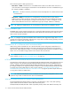
NOTE: If you will be using static HPAV, determine on which devices I/O requests are likely to converge, and then assign more aliases to those base devices. If not, HPAV might not be able to provide much improvement in host access to data in the XP1024/XP128/XP12000/XP10000. Figure 1 Static HPAV Dynamic HPAV When dynamic HPAV is used, the number of aliases for a base device may change as the number of I/O requests to the device changes.
Dynamic HPAV operations require the Workload Manager (WLM) software function provided by the host computer. For more information on WLM operations, see ”WLM Host Software Definitions for Dynamic Alias Management” on page 10 and ”System Requirements” on page 16. Figure 2 Dynamic HPAV Requirements and Restrictions The following table lists the requirements and restrictions for HPAV operations on the XP1024/XP128/XP12000/XP10000.
Table 3 Requirements and restrictions for HPAV (continued) Item Requirement and/or Restriction Functions that cannot be used concurrently with HPAV • • • • • Hitachi Multiplatform Backup/Restore (HMBR) Virtual LUN Cache LUN XP Business Copy (BC) XP Continuous Access (CA) XP Functions that can be used concurrently with HPAV • • • • • Virtual LVI Hitachi FlashAccess for S/390 SANtinel - S/390 TrueCopy (TC390) ShadowImage (SI390) NOTE: Note on GDPS: Please refer to the HP StorageWorks Continuous Acce
and/or the expected host access rates for the base devices, determine the number of aliases for each base device to meet your requirements for each base device. • Up to 255 alias devices can be assigned to one base device. In this case, however, the desired effect will not be achieved because I/O conflicts can occur with the base device and the alias devices. Therefore, the devices may be unable to receive the I/Os.
NOTE: Administrator access to the Command View XP management station or XP Remote Web Console is required to perform HPAV operations. Users without administrator access can only view HPAV information. Preparing the XP1024/XP128/XP12000/XP10000 for HPAV Operations Changing the Controller Emulation Type For HPAV operations, the XP1024/XP128/XP12000/XP10000 must have channel adapter (CHA) packages for which the 2105 or 2107 emulation type is specified.
Starting HPAV To access HPAV: 1. Click the Mainframe tab, click the Mainframe Connection button ( The HPAV window is displayed. ), and then click the HPAV tab. Figure 3 HPAV window HPAV Window Use the CU# list to select a logical CU image in the connected XP1024/XP128/XP12000/XP10000. The HPAV window displays the LDEVs (3390 LVIs only) for the selected CU image. NOTE: CU numbers included in the currently selected CU group is indicated.
The Free Volume List box displays the LDEV IDs of the unused volumes in the selected CU. Each of these free volumes can be used as an HPAV alias device. When assigning aliases to base volumes, select the alias devices from this list. • The Selected box displays the number of selected free devices and the total number of free devices in the selected CU image. For example, 8/47 indicates that eight free devices are selected out of a total of 47 free devices in the selected CU image.
To assign three aliases to each base volume, select three times as many free volumes as base volumes (for example, 3 base volumes and 9 free volumes). Figure 4 Assigning aliases 4. Click Apply on the HPAV window. When the Set HPAV confirmation dialog box is displayed, click OK to assign the new aliases as specified. To cancel your request, click Cancel.
NOTE: To set the CU numbers included in another CU group, switch the CU group by step 1 and the follow step 2 to step 4. Figure 5 Confirming new aliases Canceling Aliases CAUTION: Do not cancel aliases while I/O operations are being performed on the HPAV devices. This can cause a serious failure. To cancel aliases for volumes in the connected XP1024/XP128/XP12000/XP10000: 1.
NOTE: To cancel the alias included in another CU group, switch the CU group by step 1 and the follow step 2 to step 5. Figure 6 Canceling aliases Considerations for Defining the XP1024/XP128/XP12000/XP10000 Devices to the Host System For XRC, do not intermix the 2105 or 2107 controller emulation type with other emulation types within the XP1024/XP128/XP12000/XP10000.
NOTE: When each base device is assumed to be assigned the same number of aliases, the recommended ratio of base devices to aliases is 1:3. Verifying Base and Alias Device Definition After defining the mapping between base devices and alias devices to the host operating system (see ”Definition of XP1024/XP128/XP12000/XP10000 Base and Alias Devices” on page 22), verify that the host recognizes the XP1024/XP128/XP12000/XP10000 devices as specified.
• If the information is not correct, redefine the XP1024/XP128/XP12000/XP10000 devices to the host as described in ”Definition of XP1024/XP128/XP12000/XP10000 Base and Alias Devices” on page 22 and ”Verifying Base and Alias Device Definition” on page 23. Example: Verifying the Status of Devices Defined by CHP ID D M=CHP(80) IEE174I 10.05.
GTF I/O Tracing GTF is PAV aware. When a device number is specified for GTF I/O tracing operations, GTF determines if the device is a base PAV device and will automatically include the Alias addresses currently bound to the base device. Example: Display Command – HPAV Base Device with 5 Aliases D M=DEV(8300) IEE174I 15.33.
Example: DSESERV QPAV,SSID=xxxx Command DS QP,SSID=8300 IEE459I 15.56.03 DEVSERV QPAVS 026 HOST SUBSYSTEM CONFIGURATION CONFIGURATION -------------------------------UNIT UNIT UA NUM. UA TYPE STATUS SSID ADDR.
Example: DS QP,8300,VOLUME Command DS QP,8300,VOLUME IEE459I 16.00.15 DEVSERV QPAVS 041 HOST SUBSYSTEM CONFIGURATION CONFIGURATION -------------------------------UNIT UNIT UA NUM. UA TYPE STATUS SSID ADDR.
Example: Basic HCD Window OS/390 Release 9 HCD Command ===> ________________________________________________________________ Hardware Configuration Select one of the following. _1 1. 2. 3. 4. 5. 6. 7. 8. 9. Define, modify, or view configuration data Å Select option 1.
4. From the Add Control Unit window, enter the following information: Control unit number, Control unit type – 2105 or 2107 , and Switch connection information (see the following example). Example: Add Control Unit window Goto Filter Backup Query Help -------------------------------------------------------------------------Control Unit List Command ===> ___________________________________________ Scroll ===> CSR Select one or more control units, then press Enter. To add, use F11.
5. After defining the control unit, select the processor complex that the control unit is to be attached to (see the following example), and then select option 1 (see ”Example: Select, Change Option” on page 31). Example: Selecting the Operating System Goto Filter Backup Query Help .---------------------- Select Processor / Control Unit ----------------------.
Example: Select, Change Option Goto Filter Backup Query Help .---------------------- Select Processor / Control Unit ----------------------. | | | Command ===> .-------------- Actions on selected processors ---------------. | | | | Select proces | | | | Select by number or action code and press Enter. | | Control unit | | | | __ 1. Select (connect, change) . . . . . (s) | | | 2. Group connect . . . . . . . . . . . (g) | | / Proc. ID At | 3. Disconnect . . . . . . . . . . . .
6. Enter chpids that attach to the control unit, the logical control unit address, the device starting address, and the number of devices supported (see the following example). Example: Control Unit Chpid, CUADD, and Device Address Range Addressing Goto Filter Backup Query Help .---------------------- Select Processor / Control Unit ----------------------. | | | C .--------------------------- Add Control Unit ----------------------------. | | | | S | | | | Specify or revise the following values.
8. From the I/O Device List window, press F11 to start the Add Device dialog (see the following example). Example: I/O Device List Goto Filter Backup Query Help -------------------------------------------------------------------------I/O Device List Row 4854 of 9653 More: Command ===> ___________________________________________ Scroll ===> CSR > Select one or more devices, then press Enter. To add, use F11.ÅPress F11.
Example: Device / Processor Definition Window – Selecting the Processor ID Device / Processor Definition Row 1 of 1 Command ===> _____________________________________ Scroll ===> CSR Select processors to change device/processor definitions, then press Enter. Device number . . : 8101 Device type . . . : 3390B Number of devices . : 1 Preferred Explicit Device / Processor ID UA + Time-Out STADET CHPID + Candidate List / SYSTEM#S __ No Yes __ No Å Select processor.
Example: Device / Processor Definition Window Device / Processor Definition Row 1 of 1 Command ===> _____________________________________ Scroll ===> CSR Select processors to change device/processor definitions, then press Enter. Device number . . : 8101 Device type . . . : 3390B Number of devices . : 1 Preferred Explicit Device / Processor ID UA + Time-Out STADET CHPID + Candidate List / SYSTEM#S 01 No Yes __ NoÅ Select processor.
12. The Define Device Parameters / Features window displays the default device parameters (see the following example). NOTE: The WLMPAV parameter defaults to Yes. Example: Define Device Parameters / Features Define Device Parameters / Features Row 1 of 6 Command ===> ___________________________________________ Scroll ===> CSR Specify or revise the values below. Configuration ID . : LABSYSTM Device number . . : 8101 Device type . . .
2. After selecting the device, select option 8 to open the View Device Definition window (see the following example). Example: Actions on Selected Devices Actions on selected devices Select by number or action code and press Enter. _8 1. 2. 3. 4. 5. 6. 7. 8. 9. 10. 11. Add like . . . . . . . . . . . Change . . . . . . . . . . . . CSS group change . . . . . . . OS group change . . . . . . . . Device type group change . . . Prime serial number and VOLSER Delete . . . . . . . . . . . .
5. Review the candidate list for this device and press Enter to continue (see the following example). Example: View Device Candidate List View Device Candidate List Row 1 of 5 Command ===> _________________________________ Scroll ===> CSR The following partitions are allowed to have access to the device. Device number . : 8101 Processor ID . . : SYSTEM#S Device type . . . : 3390B Lab System - F9 - Skyline Å Press Enter to continue. ENTER to continue.
7. The View Device Parameter / Feature Definition window displays the WLMPAV device parameters (see the following example). Example: View Device Parameters ˜ View Device Parameter / Feature Definition Row 1 of 6 Command ===> _________________________________ Scroll ===> CSR Configuration ID . : LABSYSTM OS Configuration List (EDT's) Device number . . : 8100 Device type . . . : 3390B Generic / VM device type . . . . : 3390 ENTER to continue. Parameter/ Feature Value Req.
2. Use the Service Definition window to define where the service coefficient information can be found. Select option 1 to read the saved definition (see the following example). Example: WLM Choose Service Definition Window File Help -------------------------------------------------------------------------Command ===> ______________________________________________________________ ˜_____________________________________________ | Choose Service Definition | | | | Select one of the following options. | | _1 1.
4. Use the Service Coefficient/Service Definition Options window to set PAV Dynamic Alias Management (see the following example). Example: WLM Service Coefficient/Service Definition Options Window Coefficients/Options Notes Options Help ------------------------------------------------------------------------Service Coefficient/Service Definition Options Command ===> ______________________________________________________________ Enter or change the Service Coefficients: CPU IOC MSO SRB . . . . . . . .
HPAV for the XP1024/XP128/XP12000/XP10000
Index A M audience, documentation 5 MIH timer value 17 MVS commands 24 B P base and alias devices defining 27 performing HPAV operations 19 preparing host system for HPAV operations 17 prerequisites 5 C changing WLM PAV settings 39 conventions, document 6 customer support 6 S setting MIH timer value 17 WLM operation mode 17 static HPAV 12 Subscriber’s Choice for Business, HP 7 D defining base and alias devices 27 XP1024 LCU 27 displaying HPAV device parameters 36 document feedback 7 document conve