
HP ProLiant XL220a Gen8 v2 Maintenance and Service Guide


Removal and replacement procedures 46
7.
Install the server into the chassis ("Install the server" on page 26).
8. Connect all peripheral cables to the server.
9. Press the Power On/Standby button.
The server exits standby mode and applies full power to the system. The system power LED changes from
amber to green.
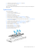
System board
To remove the component:
1. Power down the server (on page 25).
2. Disconnect all peripheral cables from the server.
3. Remove the server (on page 25).
4. Place the server on a flat, level work surface.
5. Remove the PCI riser board assembly ("PCI riser board assembly" on page 31).
6. Disconnect cables to the drive backplane, if installed ("Drive cabling" on page 59).
7. Disconnect the front panel LED board assembly cables from the system board ("Front panel LED board
assembly cabling" on page 60).
8. If installed, remove the FBWC capacitor pack ("FBWC capacitor pack" on page 34).
9. Remove the capacitor pack holder ("FBWC capacitor pack holder" on page 35).
10. Remove the processor air baffle ("Processor air baffle" on page 28).
11. Remove all DIMMs ("DIMMs" on page 30).
12. Remove all heatsinks ("Heatsink" on page 40).
13. Remove all processors ("Processor" on page 42).
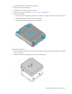
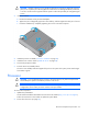
14. Disconnect all cables from the system board.
15. Remove the failed system board.