
HP ProLiant XL220a Gen8 v2 Maintenance and Service Guide


Removal and replacement procedures 33
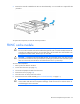
7.
Remove the controller installed on the PCI riser board assembly. A T-15 screwdriver is required for this
procedure.
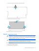
To replace the component, reverse the removal procedure.
FBWC cache module
CAUTION: The cache module connector does not use the industry-standard DDR3 mini-DIMMs.
Do not use the controller with cache modules designed for other controller models, because the
controller can malfunction and you can lose data. Also, do not transfer this cache module to an
unsupported controller model, because you can lose data.
CAUTION: In systems that use external data storage, be sure that the server is the first unit to be
powered down and the last to be powered back up. Taking this precaution ensures that the system
does not erroneously mark the drives as failed when the server is powered up.
To remove the component:
1. Back up all server data on the drive.
2. Power down the server (on page 25).
3. Disconnect all peripheral cables from the server.
4. Remove the server (on page 25).
5. Place the server on a flat, level work surface.
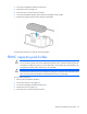
6. Remove the PCI riser board assembly ("PCI riser board assembly" on page 31).
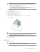
CAUTION: When connecting or disconnecting the capacitor pack cable, the connectors on the
cache module and cable are susceptible to damage. Avoid excessive force and use caution to
avoid damage to these connectors.