
HP Apollo a6000 Chassis Quick Setup Instructions
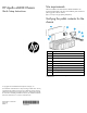

Verifying the pallet contents for the
power shelf
Item Description
1 Power shelf chassis
2 Power management module
3 AC input module
4 Power supplies*
5 Power cables*
6 HP XL Power Shelf Rack Rail Installation Instructions**
* The quantity depends on the configuration ordered.
** Not shown
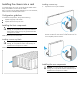
Setting up the chassis
1. Select the proper location for the chassis to be set up, based on
requirements detailed in the HP Apollo a6000 Chassis Setup and
Installation Guide on the HP website
(http://www.hp.com/go/Apollo_6000/docs).
2. Remove the packing materials from the pallet.
3. Place the chassis in the location selected in step 1.
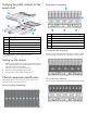
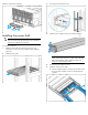
Chassis component identification
Before installing front or rear components into the chassis, review
chassis slot numbering for each component.
Server tray bay numbering
Rear panel components
Item Description
1 I/O modules (10)
2 Fan assemblies (5)
3 Power cage (Right)
4 Management module
5 Power cage (Left)
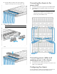
Fan assembly bay numbering
The chassis has five fan assemblies located in the rear of the chassis.
The following figure identifies the fan assemblies by device number.
I/O module bay numbering
The chassis has ten I/O module bays located in the rear of the chassis.