HP ProLiant SL4540 Gen8 Server Node Maintenance and Service Guide Abstract This guide describes identification and maintenance procedures, diagnostic tools, specifications for hardware components and software for the HP ProLiant SL4540 Gen8 Server Node. This guide is for an experienced service technician. HP assumes you are qualified in the servicing of computer equipment, trained in recognizing hazards in products, and are familiar with weight and stability precautions.
© Copyright 2012, 2014 Hewlett-Packard Development Company, L.P. The information contained herein is subject to change without notice. The only warranties for HP products and services are set forth in the express warranty statements accompanying such products and services. Nothing herein should be construed as constituting an additional warranty. HP shall not be liable for technical or editorial errors or omissions contained herein. Microsoft® and Windows® are U.S.
Contents Customer self repair ...................................................................................................................... 5 Parts only warranty service ......................................................................................................................... 5 Illustrated parts catalog ............................................................................................................... 15 Mechanical components..............................................
NMI jumper .................................................................................................................................. 55 Personality board components .................................................................................................................. 56 Cabling ..................................................................................................................................... 57 Personality board cabling ................................................
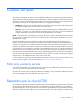
Customer self repair HP products are designed with many Customer Self Repair (CSR) parts to minimize repair time and allow for greater flexibility in performing defective parts replacement. If during the diagnosis period HP (or HP service providers or service partners) identifies that the repair can be accomplished by the use of a CSR part, HP will ship that part directly to you for replacement. There are two categories of CSR parts: • Mandatory—Parts for which customer self repair is mandatory.
Obligatoire - Pièces pour lesquelles la réparation par le client est obligatoire. Si vous demandez à HP de remplacer ces pièces, les coûts de déplacement et main d'œuvre du service vous seront facturés. Facultatif - Pièces pour lesquelles la réparation par le client est facultative. Ces pièces sont également conçues pour permettre au client d'effectuer lui-même la réparation.
In base alla disponibilità e alla località geografica, le parti CSR vengono spedite con consegna entro il giorno lavorativo seguente. La consegna nel giorno stesso o entro quattro ore è offerta con un supplemento di costo solo in alcune zone. In caso di necessità si può richiedere l'assistenza telefonica di un addetto del centro di supporto tecnico HP. Nel materiale fornito con una parte di ricambio CSR, HP specifica se il cliente deve restituire dei componenti.
defekte Teil nicht zurückschicken, kann HP Ihnen das Ersatzteil in Rechnung stellen. Im Falle von Customer Self Repair kommt HP für alle Kosten für die Lieferung und Rücksendung auf und bestimmt den Kurier-/Frachtdienst. Weitere Informationen über das HP Customer Self Repair Programm erhalten Sie von Ihrem Servicepartner vor Ort. Informationen über das CSR-Programm in Nordamerika finden Sie auf der HP Website unter (http://www.hp.com/go/selfrepair).
enviara el componente defectuoso requerido, HP podrá cobrarle por el de sustitución. En el caso de todas sustituciones que lleve a cabo el cliente, HP se hará cargo de todos los gastos de envío y devolución de componentes y escogerá la empresa de transporte que se utilice para dicho servicio. Para obtener más información acerca del programa de Reparaciones del propio cliente de HP, póngase en contacto con su proveedor de servicios local.
Neem contact op met een Service Partner voor meer informatie over het Customer Self Repair programma van HP. Informatie over Service Partners vindt u op de HP website (http://www.hp.com/go/selfrepair). Garantieservice "Parts Only" Het is mogelijk dat de HP garantie alleen de garantieservice "Parts Only" omvat. Volgens de bepalingen van de Parts Only garantieservice zal HP kosteloos vervangende onderdelen ter beschikking stellen.
No caso desse serviço, a substituição de peças CSR é obrigatória. Se desejar que a HP substitua essas peças, serão cobradas as despesas de transporte e mão-de-obra do serviço.
Customer self repair 12
Customer self repair 13
Customer self repair 14
Illustrated parts catalog Mechanical components Item Description Spare part number Customer self repair (on page 5) 1 Access panel 691280-001 Mandatory1 2 Drive blank, SFF 670033-001 Mandatory1 3 HP ProLiant SL4540 node — — 1 Mandatory—Parts for which customer self repair is mandatory. If you request HP to replace these parts, you will be charged for the travel and labor costs of this service. 2 Optional—Parts for which customer self repair is optional.
Mandatory: Zwingend—Teile, die im Rahmen des Customer Self Repair Programms ersetzt werden müssen. Wenn Sie diese Teile von HP ersetzen lassen, werden Ihnen die Versand- und Arbeitskosten für diesen Service berechnet. 2 Optional: Optional—Teile, für die das Customer Self Repair-Verfahren optional ist. Diese Teile sind auch für Customer Self Repair ausgelegt.
System components Illustrated parts catalog 17
Item Description Spare part number Customer self repair (on page 5) 4 System boards — — a) System board 687246-001 Optional2 b) System board-IVB* 755313-001 Optional2 Hot-plug solid state SATA drives — — a) 100-GB, SFF, MLC, 3G 653965-001 Mandatory1 b) 200-GB, SFF, MLC, 3G* 653966-001 Mandatory1 c) 400-GB, SFF, MLC, 3G* 653967-001 Mandatory1 d) 500-GB, SFF, MDL, 6G* 656107-001 Mandatory1 e) 1-TB, SFF, MDL, 6G* 656108-001 Mandatory1 DIMMs — — a) 4-GB, PC3L-10600R-9, single-
Item Description Spare part number Customer self repair (on page 5) k) 2.40-GHz Intel Xeon E5-2407 v2 processor* ** † 729110-001 Optional2 l) 1.70-GHz Intel Xeon E5-2450L v2 processor* ** † 729108-001 Optional2 m) 2.
Optional: Optional—Teile, für die das Customer Self Repair-Verfahren optional ist. Diese Teile sind auch für Customer Self Repair ausgelegt. Wenn Sie jedoch den Austausch dieser Teile von HP vornehmen lassen möchten, können bei diesem Service je nach den für Ihr Produkt vorgesehenen Garantiebedingungen zusätzliche Kosten anfallen. 3 No: Kein—Einige Teile sind nicht für Customer Self Repair ausgelegt. Um den Garantieanspruch des Kunden zu erfüllen, muss das Teil von einem HP Servicepartner ersetzt werden.
Illustrated parts catalog 21
Removal and replacement procedures Required tools You need the following items for some procedures: • T-10 Torx screwdriver • T-15 Torx screwdriver • HP Insight Diagnostics software ("HP Insight Diagnostics" on page 50) Preparation procedures To access some components and perform certain service procedures, you must perform one or more of the following procedures: • Power down the nodes ("Power down the node" on page 22).
This method initiates a controlled remote shutdown of applications and the OS before the node enters standby mode. Before proceeding, verify the node is in standby mode by observing that the system power LED is amber. Remove a node from the chassis 1. Power down the node (on page 22). CAUTION: To avoid damage to the node, always support the bottom of the node when removing it from the chassis. 2. Remove the node from the chassis: a. Press the release button. b. Lower the handle. c. Remove the node.
Remove the access panel To remove the component: 1. Power down the node (on page 22). 2. Remove the node ("Remove a node from the chassis" on page 23). 3. Press the access panel release button. 4. Slide the access panel towards the rear of the node, and then lift to remove the panel. Install the access panel 1. Place the access panel on top of the node. 2. Slide the access panel forward until it clicks into place.
• Always be properly grounded when touching a static-sensitive component or assembly. Symbols on equipment The following symbols may be placed on equipment to indicate the presence of potentially hazardous conditions. This symbol indicates the presence of hazardous energy circuits or electric shock hazards. Refer all servicing to qualified personnel. WARNING: To reduce the risk of injury from electric shock hazards, do not open this enclosure.
WARNING: To reduce the risk of personal injury from hot surfaces, allow the drives and the internal system components to cool before touching them. CAUTION: Do not operate the node for long periods with the access panel open or removed. Operating the node in this manner results in improper airflow and improper cooling that can lead to thermal damage. Drive blank Remove the component as indicated.
3. Remove the drive. To replace the component: CAUTION: To prevent improper cooling and thermal damage, do not operate the HP ProLiant SL4500 Series unless all drive and device bays are populated with either a component or a blank. 1. Prepare the drive.
2. Install the drive. 3. Determine the status of the drive from the drive LED definitions ("Hot-plug drive LED definitions" on page 53). DIMMs To remove the component: 1. Power down the node (on page 22). 2. Remove the node from the chassis ("Remove a node from the chassis" on page 23). 3. Remove the access panel (on page 24). 4. Remove the DIMM. To replace the component, reverse the removal procedure.
Heatsink To remove the component: CAUTION: The heatsink thermal interface media is not reusable and must be replaced if the heatsink is removed from the processor after it has been installed. 1. Power down the node (on page 22). 2. Remove the node from the chassis ("Remove a node from the chassis" on page 23). 3. Remove the access panel (on page 24). 4. Remove the heatsink. To replace the component: 1. Use the alcohol swab to remove all the existing thermal grease from the processor.
2. Remove the thermal interface protective cover from the heatsink. CAUTION: To avoid damage to the system board, processor socket, and screws, do not overtighten the heatsink screws. Use the wrench supplied with the system to reduce the possibility of overtightening the screws. 3. Install the heatsink. 4. Install the access panel (on page 24). 5. Install the node into the chassis ("Installing a node into the chassis" on page 23). 6. Power up the node.
WARNING: To reduce the risk of personal injury from hot surfaces, allow the drives and the internal system components to cool before touching them. CAUTION: To prevent possible node malfunction and damage to the equipment, multiprocessor configurations must contain processors with the same part number. CAUTION: To avoid damage to the processor and system board, only authorized personnel should attempt to replace or install the processor in this node.
6. Open each of the processor locking levers in the order indicated, and then open the processor retaining bracket. 7. Remove the processor from the processor retaining bracket. CAUTION: To avoid damage to the processor, do not touch the bottom of the processor, especially the contact area.
8. Install the processor. Verify that the processor is fully seated in the processor retaining bracket by visually inspecting the processor installation guides on either side of the processor. THE PINS ON THE SYSTEM BOARD ARE VERY FRAGILE AND EASILY DAMAGED. CAUTION: THE PINS ON THE SYSTEM BOARD ARE VERY FRAGILE AND EASILY DAMAGED. To avoid damage to the system board, do not touch the processor or the processor socket contacts. 9. Close the processor retaining bracket.
10. Press and hold the processor retaining bracket in place, and then close each processor locking lever. Press only in the area indicated on the processor retaining bracket. 11. Use the alcohol swab to remove all the existing thermal grease from the heatsink. Allow the alcohol to evaporate before continuing. 12. Apply the thermal grease to the top of the processor in the following pattern.
13. Install the heatsink. 14. Install the access panel (on page 24). 15. Install the node into the chassis ("Installing a node into the chassis" on page 23). 16. Power up the server. SFF backplane board To remove the component: 1. Power down the node (on page 22). 2. Remove the node from the chassis ("Remove a node from the chassis" on page 23). 3. Remove the access panel (on page 24). 4. Disconnect all cables from the SFF backplane board. 5.
6. Remove the board. To replace the component, reverse the removal procedure. Front panel board To remove the component: 1. Power down the node (on page 22). 2. Remove the node from the chassis ("Remove a node from the chassis" on page 23). 3. Remove the access panel (on page 24). 4. Disconnect all cables from the front panel board. 5. Remove the three screws securing the front panel board to the node. 6. Remove the board. To replace the component, reverse the removal procedure.
Personality board assembly To remove the component: 1. Power down the node (on page 22). 2. Remove the node from the chassis ("Remove a node from the chassis" on page 23). 3. Remove the access panel (on page 24). 4. Disconnect all cables connected to the top of the personality board. 5. Remove the screws securing the personality board assembly to the node. CAUTION: Do not remove the four screws that secure the personality board to the bracket.
6. Disconnect all cables connected to the underside of the personality board assembly. 7. Remove the personality board assembly. To replace the component, reverse the removal procedure. SUV interface board To remove the component: 1. Power down the node (on page 22). 2. Remove the node from the chassis ("Remove a node from the chassis" on page 23). 3. Remove the access panel (on page 24). 4. Remove the two screws securing the board to the node. 5. Disconnect all cables.
6. Remove the board. To replace the component, reverse the removal procedure. System board To remove the component: 1. Power down the node (on page 22). 2. Remove the node from the chassis ("Remove a node from the chassis" on page 23). 3. Remove the access panel (on page 24). 4. Remove all DIMMs ("DIMMs" on page 28). 5. Remove all heatsinks.
IMPORTANT: To avoid forcibly ejecting the processor, open the levers slowly. 6. Open each of the processor locking levers in the order indicated, and then open the processor retaining bracket. 7. Remove the processor from the processor retaining bracket. CAUTION: To avoid damage to the processor, do not touch the bottom of the processor, especially the contact area. 8. Remove the personality board assembly (on page 37). 9. Remove the SUV interface board (on page 38).
10. Disconnect all cables from the system board. Item Description 1 RPS cable 2 Power cable 3 SATA cables 4 HDD data LED cable 5 SUV/VGA cable 6 NIC 1 cable 7 NIC 2 cable 8 iLO cable 9 LED cable 11. Remove the header cover.
12. Remove the failed system board. To replace the system board: 1. Align the system board on the tray, and then install the header cover. 2. Install the screws. 3. Connect all cables to the system board.
4. Open each of the processor locking levers in the order indicated, and then open the processor retaining bracket. 5. Remove the clear processor socket cover. Retain the processor socket cover for future use.
6. Install the processor. Verify that the processor is fully seated in the processor retaining bracket by visually inspecting the processor installation guides on either side of the processor. THE PINS ON THE SYSTEM BOARD ARE VERY FRAGILE AND EASILY DAMAGED. CAUTION: THE PINS ON THE SYSTEM BOARD ARE VERY FRAGILE AND EASILY DAMAGED. To avoid damage to the system board, do not touch the processor or the processor socket contacts. 7. Close the processor retaining bracket.
8. Press and hold the processor retaining bracket in place, and then close each processor locking lever. Press only in the area indicated on the processor retaining bracket. 9. Install the processor socket cover onto the processor socket of the failed system board. 10. Clean the old thermal grease from the heatsink and the top of the processor with the alcohol swab. Allow the alcohol to evaporate before continuing. 11.
12. Install the heatsink. 13. Install the DIMMs (on page 28). 14. Install the personality board assembly (on page 37). 15. Install the SUV interface board (on page 38). 16. Install the access panel (on page 24). 17. Install the node into the chassis ("Installing a node into the chassis" on page 23). 18. Power up the node. After you replace the system board, you must re-enter the node serial number and the product ID. 1. During the node startup sequence, press the F9 key to access RBSU. 2.
System battery If the node no longer automatically displays the correct date and time, you might have to replace the battery that provides power to the real-time clock. Under normal use, battery life is 5 to 10 years. WARNING: The computer contains an internal lithium manganese dioxide, a vanadium pentoxide, or an alkaline battery pack. A risk of fire and burns exists if the battery pack is not properly handled. To reduce the risk of personal injury: • • • • Do not attempt to recharge the battery.
CAUTION: Any attempt to remove an installed TPM from the system board breaks or disfigures the TPM security rivet. Upon locating a broken or disfigured rivet on an installed TPM, administrators should consider the system compromised and take appropriate measures to ensure the integrity of the system data. If you suspect a TPM board failure, leave the TPM installed and remove the system board ("System board" on page 39). Contact an HP authorized service provider for a replacement system board and TPM board.
Troubleshooting Troubleshooting resources The HP ProLiant Gen8 Troubleshooting Guide, Volume I: Troubleshooting provides procedures for resolving common problems and comprehensive courses of action for fault isolation and identification, issue resolution, and software maintenance on ProLiant servers and server blades. To view the guide, select a language: • English (http://www.hp.com/support/ProLiant_TSG_v1_en) • French (http://www.hp.com/support/ProLiant_TSG_v1_fr) • Spanish (http://www.hp.
Diagnostic tools HP ROM-Based Setup Utility RBSU is a configuration utility embedded in HP ProLiant servers that performs a wide range of configuration activities that can include the following: • Configuring system devices and installed options • Enabling and disabling system features • Displaying system information • Selecting the primary boot controller • Configuring memory options • Language selection For more information on RBSU, see the HP ROM-Based Setup Utility User Guide on the Documen
• From within the iLO user interface • From within HP Insight Diagnostics (on page 50) HP Insight Remote Support software HP strongly recommends that you register your device for remote support to enable enhanced delivery of your HP Warranty, HP Care Pack Service, or HP contractual support agreement.
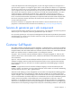
Component identification Front panel components Item Description 1 Hard drive bay 1 2 Hard drive bay 2 3 Node release button 4 USB connectors (2) 5 VGA connector Front panel LEDs and buttons Item Description Status 1 UID LED button Blue = Activated Flashing blue = System is being remotely managed or firmware update is in progress.
Item Description Status Flashing amber = System degraded Flashing red = System critical 3 Power On/Standby button and system power LED Green = System on Amber = System is in Standby mode, but power is still applied. Off = Power is not connected, or power supply has failed. Hot-plug drive LED definitions Item LED Status Definition 1 Locate Solid blue The drive is being identified by a host application. Flashing blue The drive carrier firmware is being updated or requires an update.
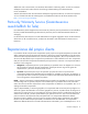
System board components Item Description 1 HDD data LED backplane connector 2 Power connector 3 Processor socket 2 4 Processor 1 DIMM slots (6) 5 SATA HDD connector 1 6 SATA HDD connector 2 7 Reserved connector 8 Reserved connector 9 Reserved connector 10 Reserved connector 11 HDD data LED connector 12 MicroSD card slot 13 USB/VGA connector 14 Personality board connector 1 15 NMI jumper 16 NIC 1 connector 17 NIC 2 connector 18 iLO connector 19 LED power connector 20
Item Description 31 VGA connector 32 Front LED connector DIMM slots DIMM slots are numbered sequentially (1 through 6) for each processor. The supported AMP modes use the letter assignments for population guidelines.
drivers, and applications. Many crashes can freeze a system, requiring you to do a hard reset. Resetting the system erases any information that would support root cause analysis. Systems running Microsoft® Windows® experience a blue-screen trap when the OS crashes. When this happens, Microsoft® recommends that system administrators perform an NMI event by temporarily shorting the NMI header with a jumper. The NMI event enables a hung system to become responsive again.
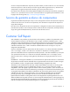
Cabling Personality board cabling To access cables underneath the personality board assembly, see "Personality board assembly (on page 37)." Item Description 1 NIC 2 (1 Gb) 2 NIC 1 (1 Gb) 3 iLO HDD data LED cabling The HDD data LED cable routes underneath the SATA cables and power cable. Connect and route the cables in the following order: 1. HDD data LED cable (bottom) 2. SATA cables 3.
SATA cabling To access cables underneath the personality board assembly, see "Personality board assembly (on page 37)." The SATA cables route over the HDD data LED cable and underneath the power cable. Connect and route the cables in the following order: 1. HDD data LED cable (bottom) 2. SATA cables 3. Power cable Internal power cabling The power cable routes over the HDD LED cable and SATA cables. Connect and route the cables in the following order: 1. HDD data LED cable (bottom) 2.
RPS cabling The RPS cable routes with the front LED cable underneath the SATA board power cable and USB/VGA cable. Connect and route the cables in the following order: 1. RPS cable and front LED cable (bottom) 2. SATA power board cable 3. USB/VGA cable Front I/O cabling To access cables underneath the personality board assembly, see "Personality board assembly (on page 37)." The front LED cable routes with the RPS cable underneath the SATA board power cable and the USB/VGA connector cable.
SATA board power cabling The SATA board power cable routes on top of the RPS cable and front LED cable, and underneath the USB/VGA cable. Secure the SATA board power cable in the plastic clip provided. Connect and route the cables in the following order: 1. RPS cable and front LED cable (bottom) 2. SATA power board cable, secured in the plastic clip 3. USB/VGA cable USB/VGA cabling To access cables underneath the personality board assembly, see "Personality board assembly (on page 37).
Specifications Environmental specifications Specification Value Temperature range* Operating 10°C to 35°C (50°F to 95°F) Shipping -40°C to 70°C (-40°F to 158°F) Maximum wet bulb temperature 28°C (82.4°F) Relative humidity (noncondensing)** Operating 10% to 90% Nonoperating 5% to 95% * All temperature ratings shown are for sea level. An altitude derating of 1°C per 300 m (1.8°F per 1,000 ft) to 3,048 m (10,000 ft) is applicable. No direct sunlight allowed.
Acronyms and abbreviations CSR Customer Self Repair NMI nonmaskable interrupt RPS redundant power supply SUV serial, USB, video Acronyms and abbreviations 62
Documentation feedback HP is committed to providing documentation that meets your needs. To help us improve the documentation, send any errors, suggestions, or comments to Documentation Feedback (mailto:docsfeedback@hp.com). Include the document title and part number, version number, or the URL when submitting your feedback.
Index A E access panel 24 electrostatic discharge 24 environmental requirements 61 environmental specifications 61 B backplane board 35 batteries, replacing 47 battery 47 buttons 22, 52 C cables 57 cabling 57, 58, 59, 60 cabling, front I/O 59 cabling, internal power 58 cabling, personality board 57 cabling, RPS 59 cabling, SATA 58 cabling, SATA board power 60 cabling, USB 60 cabling, VGA 60 Care Pack 51 cautions 25 chassis, installing server 23 chassis, removing server 23 components 15, 52 components,
N NMI header 55 troubleshooting 49 troubleshooting resources 49 Trusted Platform Module (TPM) 47 P U personality board 37, 57 personality board cabling 57 personality board components 56 power cabling, internal 58 powering down 22 preparation procedures 22 problem diagnosis 49 processor 30 USB cabling 60 utilities 50 utilities, deployment 50 R RBSU (ROM-Based Setup Utility) 50 removal and replacement procedures 22 removing the access panel 24 replacement procedures 22 required tools 22 ROM-Based Setup