
HP ProLiant SL390s G7 1U Half-width Server Installation Sheet
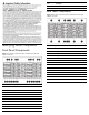
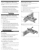
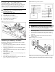
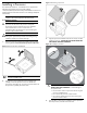
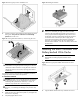
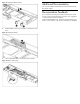

Figure 11 Removing the processor installation tool
5. Close the processor socket retaining bracket and the processor
locking lever. The processor socket cover is automatically
ejected. Remove the cover.
Figure 12 Closing the bracket and lever, and removing the cover
CAUTION: Be sure to close the processor socket retaining
bracket before closing the processor locking lever. The lever
should close without resistance. Forcing the lever closed can
damage the processor and socket, requiring system board
replacement.
For processor removal, reverse the above installation procedures,
using the processor tool to remove the processor.
To install the heatsink:
CAUTION: Heatsink screws should be tightened and loosened
in opposite sequence. Do not overtighten the screws as this
can damage the system board, connectors, or screws. A
maximum torque of 6-8 in-lb is set for the system.
CAUTION: Be sure that the heatsink sits squarely on the
processor, or overheating and damage to the processor may
occur.
1. Position the heatsink on the processor backplate.
2. Tighten the first screw about three quarters in, then tighten the
second screw completely.
3. Completely tighten the first screw.
Figure 13 Installing the heatsink
IMPORTANT: If the heatsink has been removed for any
reason, it is critical that you apply more thermal interface
material to the integrated heat spreader on the processor to
ensure proper thermal bonding between the processor and
the heatsink. Clean the contact surface of both the processor
and heatsink with an alcohol pad, then re-apply an HP-
approved thermal interface material before reinstalling the
processor. Use a pattern of five dots when applying the
thermal interface material—one dot in the center, and one dot
at each corner.
Installing the RAID Controllers with
Battery-backed Write Cache
IMPORTANT: Remove the plastic bracket from the metal
bracket before installing the plastic bracket into the
chassis.
1. Unfasten the screws and lift the plastic BBWC bracket out.
Figure 14 Removing the plastic BBWC bracket from the metal
bracket
2. Align the BBWC bracket to the tray and fasten the screws.