
HP ProLiant SL210t Gen8 Plus Server Maintenance and Service Guide


Removal and replacement procedures 49
c.
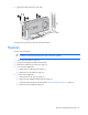
Finish the installation by completely tightening the screws in the same sequence.
9. Install DIMMs.
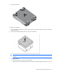
10. Connect cables to the system board ("System board components" on page 61).
11. Install the FlexibleLOM riser cage.
12. In a 1U node configuration:
a. Install the PCI riser cage.
b. Install the 1U air baffle
c. Install the 1U cable guard.
13. In a 2U node configuration:
a. Install the 2U air baffle.
b. Connect the Mini-SAS cable.
c. Install the 2U adapter board bracket.
d. Install the PCI riser cage.
e. If a GPU is installed, connect the 2U adapter cable to the GPU power cable.
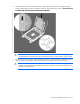
14. Install the node into the chassis.
15. Connect all peripheral cables to the node.
16. Power up the node ("Power up the nodes" on page 22).
After you replace the system board, you must re-enter the node serial number and the product ID.
1. During the node startup sequence, press the F9 key to access RBSU.
2. Select the Advanced Options menu.
3. Select Service Options.
4. Select Serial Number. The following warnings appear:
WARNING! WARNING! WARNING! The serial number is loaded into the system during
the manufacturing process and should NOT be modified. This option should only
be used by qualified service personnel. This value should always match the
serial number sticker located on the chassis.