
HP ProLiant SL210t Gen8 Plus Server Maintenance and Service Guide


Removal and replacement procedures 38
6.
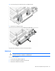
Install the heatsink:
a. Position the heatsink on the processor backplate.
b. Tighten one pair of diagonally opposite screws halfway, and then tighten the other pair of screws.
c. Finish the installation by completely tightening the screws in the same sequence.
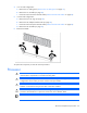
7. In a 1U node configuration:
a. Install the 1U air baffle.
b. Install the 1U cable guard.
8. In a 2U node configuration:
a. Install the 2U air baffle.
b. Connect the Mini-SAS cable.
c. Install the 2U adapter board bracket.
d. Install the PCI riser cage.
e. If a GPU is installed, connect the 2U adapter cable to the GPU power cable.
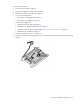
9. Install the node into the chassis.
10. Connect all peripheral cables to the node.
11. Power up the node ("Power up the nodes" on page 22).
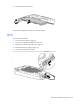
FlexibleLOM adapter
To remove the component:
1. Power down the node (on page 22).
2. Disconnect all peripheral cables from the node.
3. Remove the node from the chassis (on page 23).
4. In a 2U node configuration, remove the PCI riser cage (on page 24).