
HP Universal Switch Rail Kit Installation Instructions
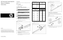

HP Universal Switch Rail Kit
Option Installation
Instructions
Legal notices
© Copyright 2009 Hewlett-Packard Development Company, L.P.
The information contained herein is subject to change without notice. The
only warranties for HP products and services are set forth in the express
warranty statements accompanying such products and services. Nothing
herein should be construed as constituting an additional warranty. HP shall
not be liable for technical or editorial errors or omissions contained herein.
Overview
This document contains instructions for installing HP Universal Switch
Rail Kit.
Kit Contents
• HP Universal Switch Rail Kit
• Installation Instructions
Important Safety Information
Refer to the Important Safety Information document included with the
switch.
CAUTION: Electrostatic discharge (ESD) can damage
electronic components. Be sure you are properly
grounded (earthed) before beginning any installation
procedure.
Installation Guidelines
This installation is to be performed by qualified individuals who are
knowledgeable of the procedures, precautions, and hazards
associated with equipment containing hazardous electrical circuits.
WARNING: Failure to properly turn off the switch before
you open the switch may cause serious damage as well
as bodily harm.
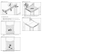
Configuring the Switch Rail Kit
1. Install the left mounting ear that comes with the switch, do not
install the right ear, it will not be used.
Figure 1 Installing the Left Ear
2. Measure and record the distance from the back of the left
mounting ear to the rear of the switch.
3. Measure and record the width of the switch chassis (not
including the ear).
4. Use Table 1 to determine the number of shims to use on each
rail. Then use Table 2 to determine the location of the spacer
for the left and right rail.
Table 1
.Switch Width
Width of Switch (mm)
Number of Shims per
Side
447.0 - 444.0 0
443.9 - 441.0 1
440.9 - 438.0 2
437.9 - 435.0 3
434.9 - 432.0 4
431.9 - 429.0 5
Table 2 Switch Length
Spacer Position
Length From Back of Left
Ear to Rear of Switch
(mm)
Left Right
110.3 - 141.2 16 & 18 2 & 4
141.2 - 172.2 15 & 17 3 & 5
172.2 - 203.1 14 & 16 4 & 6
203.1 - 234.1 13 & 15 5 & 7
234.1 - 265.0 12 & 14 6 & 8
265.0 - 296.0 11 & 13 7 & 9
296.0 - 326.9 10 & 12 8 & 10
326.9 - 357.9 9 & 11 9 & 11
357.9 - 388.8 8 & 10 10 & 12
388.8 - 419.8 7 & 9 11 & 13
419.8 - 450.7 6 & 8 12 & 14
450.7 - 481.7 5 & 7 13 & 15
481.7 - 512.6 4 & 6 14 & 16
512.6 - 543.6 3 & 5 15 & 17
543.6 - 574.5 2 & 4 16 & 18
574.5 - 605.5 1 & 3 17 & 19
5. Install the adjustable side spacer with correct number of shims
in the positions determined in step 4, fasten with the included
screws.
Figure 2 Installing the side spacer
6. Install the Mylar air dam in at the front of the right rail.
Figure 3 Installing the Air Dam
Installing the Switch Rail Kit
There are 2 “L” holes and 2 “R” holes in each rail. Please note to
align left side of switch with 2”L”holes and right side of switch with 2
“R” holes.
Figure 4 Universal Switch Rail
To install the rail:
1. Install the cage-nuts on the rack column, then align the rail with
the rack column and fasten the screws.
Part number: 592979-001
October 2009 (First edition)