
HP ProLiant SL160z G6 Server Installation Sheet


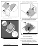
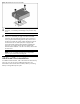

Figure 8 Reinserting the processor
3. Align the processor installation tool with the socket, and then
install the processor. THE PINS ON THE SYSTEM BOARD ARE
VERY FRAGILE AND EASILY DAMAGED.
Figure 9 Installing the processor
CAUTION: THE PINS ON THE SYSTEM BOARD ARE VERY
FRAGILE AND EASILY DAMAGED. To avoid damage to
the system board:
• Never install or remove a processor without using the
processor installation tool.
• Do not touch the processor socket contacts.
• Do not tilt or slide the processor when lowering the
processor into the socket.
4. Press the tabs on the processor installation tool to separate it
from the processor, and then remove the tool.
Figure 10 Removing the tool
5. Close the processor socket retaining bracket and the processor
locking lever. The processor socket cover is automatically
ejected. Remove the cover.
Figure 11 Closing the bracket and lever, removing cover
CAUTION: Be sure to close the processor socket
retaining bracket before closing the processor locking
lever. The lever should close without resistance. Forcing
the lever closed can damage the processor and socket,
requiring system board replacement.
For processor removal, reverse the above installation procedures
using the processor tool to remove the processor.
CAUTION: To prevent the heat sink from tilting to one side
during installation/removal, turn each screw a couple of
turns, alternatively between both of them, and then apply the
final torque. Do not over tighten the spring loaded screws to
prevent them from breaking off. A maximum torque of 4.5
inch-lb is set for each screw.