
HP ProLiant SL160z G6 Server Installation Sheet


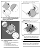
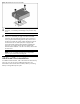

Figure 5 Installing the hard disk drive
Installing the Memory Module
The following guidelines must be followed when memory modules
are being added or replaced:
Support ZKPG DDR3 DIMMs using 1G, 2G, 4G, 8G DDR3 DRAMs.
• Supported configuration:
o One DIMM per processor: J44 for CPU1; J25 for CPU2.
o Three DIMMs per processor: J44, J46, J48 for CPU1; J21,
J23, J25 CPU2.
o Six DIMMs per processor: J44, J43, J46, J45, J48, J47 for
CPU1; J21, J22, J23, J24, J25, J26 for CPU2.
o Nine DIMMs per processor: J44, J43, J74, J46, J45, J75,
J48, J47, J76 for CPU1; J21, J22, J79, J23, J24, J78,
J25, J26, J77 for CPU2.
CAUTION: DIMMs can be damaged by improper handling.
Always use an anti-static wrist strap and grounding mat, and
discharge static electricity before touching DIMMs.
To install the memory module:
1. Align the notch on the bottom edge of the module with the
keyed surface of the DIMM slot and then press the module fully
into the slot.
2. Firmly press the holding clips inward to secure the memory
module in place.
Figure 6 Installing the memory module
DIMM slots are structured to ensure proper installation. If you insert a
DIMM but it does not fit easily into the slot, you may have inserted it
incorrectly. Reverse the orientation of the DIMM and insert it again.
Installing the Processor
The HP ProLiant SL160z G6 server supports Intel
®
Nehalem
®
5500
Series Processors High Wattage 80W and Intel
®
Xeon
®
5600 Series
Processors High Wattage 95W, and Intel
®
Nehalem
®
5500 Series
Processors Low Wattage 60W and Intel
®
Xeon
®
5600 Series
Processors Low Wattage 40W.
To install the processor:
CAUTION: Use the process install tool to insert the
processor into the socket. The processor and system
board spare part kits contain the processor install tool
and instructions on how to use the tool. It is important to
follow the instructions to prevent damage to the pins in
the processor socket.
CAUTION: Failure to completely open the processor
locking lever prevents the processor from seating during
installation, leading to hardware damage.
1. Open the processor locking lever and the processor socket
retaining bracket. Do not remove the processor socket cover.
Figure 7 Opening the lever and bracket
IMPORTANT: Be sure the processor remains inside the
processor installation tool.
2. If the processor has separated from the installation tool,
carefully re-insert the processor in the tool. Handle the
processor by the edges only, and do not touch the bottom of
the processor, especially the contact area.