HP ProLiant SL160s G6 Server Installation Instructions Part Number 635239-002
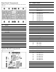
Identifying server components Front Panel Components SL160s G6 Server Front Panel Components Figure 1 Front panel components of the s6500 chassis with 4 SL160s G6 servers 2 Item Description 1 Serial port 2 VGA port 3 Top: USB 2.0 Port Bottom: USB 2.
Rear Panel Components Figure 2 Rear panel components of the s6500 chassis with 4 SL160s G6 servers Item Designator Description 1 J2 Serial Port (COM1) 2 J1 VGA Port 3 J8 Top: USB 2.0 Port Bottom: USB 2.
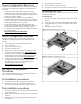
. Server Configuration Resources In addition to this Installation Sheet, other resources are available for more information regarding the configuration and maintenance of your server: Reinstall the tray into the chassis. 5. Connect all external cables to the system. 6. Press the power button on the front panel to turn on the server.
Installing the Memory Module Installing the Hard Disk Drive One SL160s G6 server tray can accommodate up to 6 LFF SATA, 4 LFF SAS, or 8 SFF SATA/SAS Non Hot-Plug hard disk drives, and the chassis can accommodate 4 server trays for up to 24 LFF SATA or 32 SFF Non Hot-Plug hard disk drives. The server supports both SAS and SATA hard disk drives.
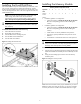
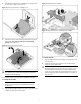
Installing the Processor 3. NOTE: If one processor is being installed, it should be installed in the socket furthest from the IOH/chipset. Align the processor installation tool with the socket and install the processor. THE PINS ON THE SYSTEM BOARD ARE VERY FRAGILE AND EASILY DAMAGED. Figure 10 Installing the processor To install the new processor: CAUTION: Failure to completely open the processor locking lever prevents the processor from seating during installation, leading to hardware damage. 1.
4. Press the tabs on the processor installation tool to separate it from the processor, and then remove the tool. Figure 13 Installing the PCI air baffle Figure 11 Removing the processor installation tool Figure 14 Detail information for installing the PCI air baffle 5. Close the processor socket retaining bracket and the processor locking lever. The processor socket cover is automatically ejected. Remove the cover.
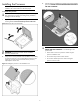
IMPORTANT: The one close to front panel is processor 2 and the other one is processor 1. During install the heat sink, make sure the side with a triangle logo close to the DIMMs. Figure 15 Installing the heat sink assembly Installing the CPU Air Baffle NOTE: The CPU air baffle is required for proper thermal solution. To install the CPU air baffle: 1. Align the CPU air baffle to the tray. 2. Secure the latches to the tray as described in below figure. 3.