
ProLiant ML570 Generation 4 Server Maintenance and Service Guide
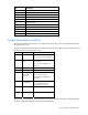
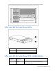

Server component identification 81
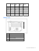
Item Description
24 Fan board signal connector
25 Processor socket 3
26 Processor socket 2
27 Fan board signal connector
28 Fan board power connector
29 Processor socket 1
30 Power connector
31 Fan connector
32 Fan connector
33 Power supply signal connector
34 Internal USB connector
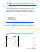
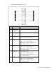
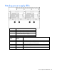
System maintenance switches
The system maintenance switch (SW1) is an eight-position switch that is reserved. The default position for
all eight positions is Off.
The system maintenance switch (SW2) is an eight-position switch that is used for system configuration. The
default position for all eight positions is Off.
Position Description Function
S1 iLO 2 security Off = iLO 2 security is enabled
On = iLO 2 security is disabled
S2 Configuration
lock
Off = System configuration can
be changed
On = System configuration is
locked
S3 Reserved Reserved
S4 Reserved Reserved
S5 Password
protection
override
Off = No function
On = Clears power-on
password and administrator
password
S6 Invalid
configuration
Off = Normal
On = ROM treats system
configuration as invalid
S7 Reserved Reserved
S8 Reserved Reserved
When the system maintenance switch position 6 is set to the On position, the system is prepared to erase
all system configuration settings from both CMOS and NVRAM.