
ProLiant ML570 Generation 4 Server Maintenance and Service Guide

Removal and replacement procedures 54
12.
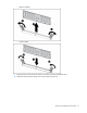
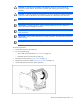
Remove the cable from the clip on the inside wall of the chassis.
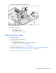
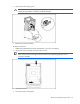
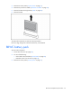
13. Use the T-15 Torx screwdriver to remove the screw from the video/USB connector.
14. Lift up and rotate the video connector out of the opening on the front panel.
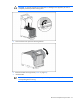
15. Remove the video/USB cable from the chassis.
To replace the component, reverse the removal procedure.
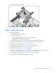
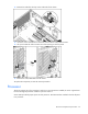
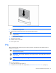
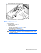
Processor
The server supports up to four processors. With two or more processors installed, the server supports boot
functions through the processor installed in processor socket 1.
Server PPMs provide the proper power to each processor. Each PPM must be installed in the slot adjacent
to its processor.