
ProLiant ML570 Generation 4 Server Maintenance and Service Guide

Removal and replacement procedures 53
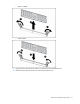
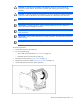
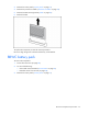
6.
Remove the memory board cage.
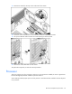
To replace the component, reverse the removal procedure.
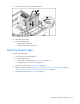
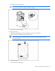
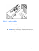
Video/USB connector
To remove the component:
1. Power down the server (on page 28).
2. Do one of the following:
o Unlock and remove the bezel ("Tower bezel" on page 29).
o Extend the server from the rack (on page 28).
3. Remove the tape drive ("Tape drive" on page 32) or tape drive blank (on page 31).
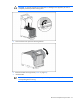
4. If the server is rack mounted, remove the rack bezel ("Rack bezel" on page 33).
5. Remove the access panel ("Access panel" on page 31).
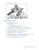
6. Remove the processor air baffle ("Processor air baffle" on page 38).
7. Remove the front fan cage. ("Front fan cage" on page 39)
8. Remove the center wall. ("Center wall" on page 41)
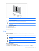
9. Remove all memory boards ("Removing and installing a memory board (hot-plug)" on page 47,
"Removing and installing a memory board (non-hot-plug)" on page 50).
10. Remove the memory board cage. ("Memory board cage" on page 52)
11. Disconnect the video/USB cable from the system board.