
ProLiant ML570 Generation 3 Server User Guide


Hardware options installation 67
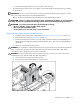
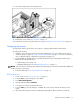
10.
Move the locking switch to the locked position.
NOTE: In hot-plug procedures, all LEDs now turn off except the board status LED, which flashes green while
the board is rebuilding. This process may take several minutes.
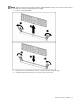
11. Observe the LEDs on the top of the memory board to be sure that the memory is functioning properly
("Memory board LEDs and components" on page 20). The LED states will be valid when the memory
board has finished rebuilding.
12. Replace the access panel ("Access panel" on page 31).
13. Reinstall the server into the rack (rack servers only) ("Installing the server into the rack" on page 37).
Removing and installing a memory board (non-hot-plug)
1. Extend the server from the rack, if applicable ("Extending the server from the rack" on page 27).
2. Remove the access panel ("Access panel" on page 31).
3. Determine which memory board is to be removed by locating the memory board that displays an
amber board status LED. Take note of the failed DIMM, if applicable.
4. Power down the server (on page 27).
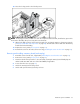
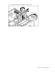
5. Unlock the memory board locking switch.
6. Unlock and open the memory board ejector lever.