
ProLiant ML570 Generation 2 Server Maintenance and Service Guide

Connectors, LEDs, and Switches
System Board
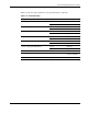
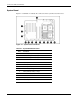
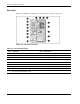
Figure 4-1 and Table 4-1 identify the connectors on the system board of the server.
Figure 4-1: System board connectors
Table 4-1: System Board Connectors
Item Connector
1 Secondary IDE (non-bootable)
2 Remote management (30-pin)
3 Remote management (16-pin)
4 I/O fans
5 System power
6 SCSI A (blue)
7 SCSI B (yellow)
8 Power backplane signal
9 Primary IDE (bootable) (orange)
10 Diskette drive (purple)
11 Processor fans
12 System power
13 PCI backplane
4-2 HP ProLiant ML570 Generation 2 Server Maintenance and Service Guide