
ProLiant ML570 Generation 2 Server Maintenance and Service Guide


Removal and Replacement Procedures
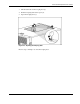
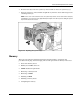
Parts of the Memory Board
Figure 2-9 and Table 2-1 identify the parts of the memory board.
Figure 2-9: Parts of the memory board
Table 2-1: Parts of the Memory Board
Item Description
1 DIMM slot 1, bank A (populated)
2 DIMM slot 2, bank A (populated)
3 DIMM slot 3, bank B
4 DIMM slot 4, bank B
5 DIMM slot 5, bank C
6 DIMM slot 6, bank C
7 DIMM slot 7, bank D*
8 DIMM slot 8, bank D*
9 LEDs
10 Locking switch
11 Release latches
12 Ejector levers
*When the server is configured for online spare memory, Bank
D on memory board 1 is the online spare bank.
2-12 HP ProLiant ML570 Generation 2 Server Maintenance and Service Guide