
Compaq ProLiant ML530 Setup and Installation Guide


Server Installation 3-19
Compaq Confidential – Need to Know Required
Writer: Tricia Acevedo Project: Compaq ProLiant ML530 Setup and Installation Guide Comments:
Part Number: 139006-002 File Name: d-ch3 Installation.doc Last Saved On: 6/15/00 9:02 AM
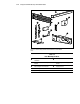
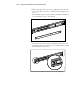
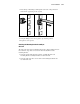
You will use a total of four 8-32 x 1/4-inch slotted screws to fasten the
bracket rail to the mounting bracket. When all five screws are fastened,
the mounting bracket and bracket rail form a mounting bracket slide
assembly that you will attach to the rack.
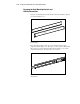
9. Repeat steps 4 through 7 with the other bracket rail and mounting
bracket. You now have a pair of mounting bracket slide assemblies to be
attached to the rack.
Attaching the Mounting Bracket Slide Assembly
to the Rack
WARNING: To reduce the risk of personal injury or damage to the equipment,
be sure that the rack leveling feet are extended to the floor and support the full
weight of the rack. Each rack must be level and stable. Racks that are not
coupled together require the installation of stabilizers. This must be done before
you perform any work on the rack.
See the Rack Planning and Installation Guide, shipped with your rack, for more
information on leveling feet and stabilizers.
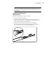
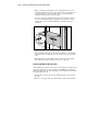
Measuring with the Template
The template provided with the server provides an easy and reliable way to
properly position the server in the rack. Use the tabs on the template to
suspend it from the lower hole of a two-hole set of perforations in the vertical
side rails. Pencil mark the attachment points for the mounting bracket
assemblies, the cage nuts for the face-plate thumbscrews, and the top of the
server. Use the tick marks on the rack side rails to ensure level installation of
the server. Refer to the illustrations and instructions printed on the template.
IMPORTANT: Determine the server’s place in the rack before you start installing the
mounting bracket assemblies. Always mount the heaviest item on the bottom of the rack
and work from the bottom to the top.
1. Starting at the bottom of the rack, or at the top of a previously mounted
component, measure the screw hole locations for the server’s mounting
bracket assemblies. Pencil mark the locations on the outside of the rack.
Do this on both the front and the back of the rack.
IMPORTANT: The template is two-sided (front and back) and printed with arrows that
show you where the screws will be inserted, both for the mounting bracket assemblies
and for the thumbscrews that will secure the server’s face plate to the front of the rack.
Align the template carefully with the holes on the rack to determine the exact placement
of the screws.