
HP ProLiant ML370 Storage Server Installation Instructions (November 2004)
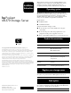

Item Description
1 x4 PCI Express expansion slot
2 100-MHz PCI-X expansion slots
3 Unit ID LED
4 Ethernet 10/100/1000 port
5 iLO management port
6 Parallel connector
7 Video connector
8 T-15 Torx screwdriver
9 Auxillary VHDCI SCSI blank
- Mouse connector
q Keyboard connector
w Serial connector B
e Serial connector A
r USB connectors
t Primary hot-plug power supply
y Redundant hot-plug power supply
Callouts
Front panel Rear panel
Follow the steps in this section to set up a tower model server.
WARNING : To reduce the risk of electric shock, fire, or
damage to the equipment, do not plug telephone or
telecommunications connectors into RJ-45 connectors.
1. Connect network cable and any peripheral devices to the server.
2. Connect the power cord to the back of the server.
3. Connect the power cord to the AC power source.
WARNING: To reduce the risk of personal injury or damage
to the equipment:
• Do not disable the power cord grounding plug. The
grounding plug is an important safety feature.
• Plug the power cord into a grounded (earthed) electrical
outlet that is easily accessible at all times.
• Unplug the power cord from the power supply to disconnect
power to the equipment.
• Do not route the power cord where it can be walked on
or pinched by items placed against it. Pay particular
attention to the plug, electrical outlet, and the point where
the cord extends from the server.
Installing a storage server (tower)
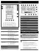
Item Description
1 UID switch and LED Blue = Activated
Flashing = System managed remotely
Off = Deactivated
2 Int system health LED Green = Normal (system on)
Amber = System health is degraded
Red = System health is critical
Off = Normal (system off)
3 Ext system health LED Green = Normal (system on)
Amber = Redundant power supply failure
Red = Power supply failure.
No operational power supplies.
Off = Normal (system off)
4 NIC link/activity LED Green = Linked to network
Flashing green = Linked with activity
on the network
Off = No network connection
5 Power on/Standby Amber = System has AC power
button/LED and is in standby mode
Green = System has AC power
and is turned on
Off = System has no AC power
6 Diskette drive*
7 Removable media bays
8 Hot-plug SCSI hd bays
(SCSI IDs 0 through 5)