
Compaq ProLiant ML350 Generation 2 Server Maintenance and Service Guide

Removal and Replacement Procedures
Compaq ProLiant ML350 Generation 2 Server Maintenance and Service Guide 2-33
COMPAQ CONFIDENTIAL Codename: Forge Part Number: 236634-002 Last Saved On: 5/14/02 12:00 PM
System Board
To remove the system board:
1. Complete the preparation procedures. Refer to “Preparation Procedures” earlier in this
chapter.
2. Open the bezel door. Refer to “Bezel Door” earlier in this chapter.
3. Remove the access panel. Refer to “Access Panel” earlier in this chapter.
4. Remove the air baffle. Refer to “Air Baffle” earlier in this chapter.
5. Remove the system fan module. Refer to “System Fan Module” earlier in this chapter.
6. Disconnect all power cables, device cables, and the power button cable from the system
board. Refer to “Cable Routing Diagrams” earlier in this chapter.
7. Remove the Server Feature Board. Refer to “Server Feature Board” earlier in this
chapter.
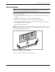
8. Remove all expansion board(s) and memory modules. Refer to “Expansion Board” and
“Memory Modules” earlier in this chapter.
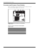
9. Remove all processors and Processor Power Modules (PPMs). Refer to “Processors and
Processor Power Modules” earlier in this chapter.
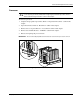
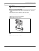
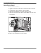
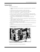
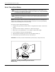
10. With a Torx T-15 screwdriver, remove the four screws securing the system board to the
chassis (1).
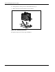
11. Push the system board toward the front of the unit until the board stops (2).
12. Holding the system board from the edges, lift up the system board, and then pull it away
from the chassis (3).
1
2
3
1
Figure 2-29: Removing the system board
To replace the system board, reverse steps 2 through 12.