
ProLiant ML310 Generation 2 Server Maintenance and Service Guide
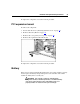
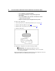
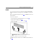

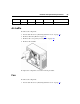
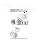
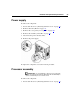
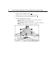

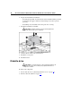
Table Of Contents
- HP ProLiant ML310 Generation 2 Server Maintenance and Service Guide
- Notice
- Contents
- Illustrated parts catalog
- Removal and replacement procedures
- Required tools
- Safety considerations
- Preparation procedures
- Bezel
- Hot-plug SCSI hard drive
- Hot-plug SATA/SAS hard drive
- Access panel
- PCI expansion board
- Battery
- DIMM
- Air baffle
- Fan
- Power supply
- Processor assembly
- Diskette drive
- CD-ROM/DVD-ROM drive
- Installing a full-height tape drive option
- Full-height tape drive
- Power button/LED board
- Hard drive (non-hot-plug)
- Hot-plug SCSI backplane
- Hot-plug SATA or SAS backplane
- System board
- Server cabling
- Diagnostic tools
- Server component identification
- Front panel components
- Front panel LEDs and buttons
- Rear panel components
- Rear panel LEDs and buttons
- System board components
- System board LEDs
- System LEDs and internal health LED combinations
- SCSI IDs
- Hot-plug SCSI hard drive LEDs
- Hot-plug SCSI hard drive LED combinations
- Hot-plug SATA or SAS IDs
- SATA or SAS hard drive LEDs
- Fan locations
- Specifications
- Acronyms and abbreviations
- Index

24 HP ProLiant ML310 Generation 2 Server Maintenance and Service Guide
DIMM installation guidelines
Observe the following guidelines when installing additional memory:
• DIMMs installed in the server must be Unbuffered DDR DRAM, 2.5 volts,
64 bits wide, and ECC.
• If only a single DIMM is installed, it must be installed in slot 1A.
• All DIMMs installed must be the same speed.
BIOS detects the DIMM population and sets the system as follows:
• Single-channel mode: DIMMs installed in one channel only.
• Dual-channel asymmetric mode: DIMMs installed in both channels but of
unequal capacities per channel.
• Dual-channel interleaved mode: DIMMs installed in both channels with
equal channel capacities.
The following table lists some, but not all, possible configurations. For best
performance, HP recommends dual-channel interleaved mode configurations.
Slot 1A Slot 2A Slot 3B Slot 4B Total memory Mode
128 MB — — — 128 MB Single-channel
128 MB — 128 MB — 256 MB Dual-channel interleaved
128 MB 128 MB 128 MB — 384 MB Dual-channel
asymmetric
128 MB 128 MB 128 MB 128 MB 512 MB Dual-channel interleaved
256 MB — — — 256 MB Single-channel
256 MB — 256 MB — 512 MB Dual-channel interleaved
512 MB — — — 512 MB Single-channel
512 MB — 512 MB — 1 GB Dual-channel interleaved
1 GB — — — 1 GB Single-channel
1 GB — 1 GB — 2 GB Dual-channel interleaved
1 GB 1 GB 1 GB — 3 GB Dual-channel
asymmetric