
ProLiant ML310 Generation 2 Server Maintenance and Service Guide

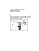
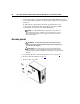
Table Of Contents
- HP ProLiant ML310 Generation 2 Server Maintenance and Service Guide
- Notice
- Contents
- Illustrated parts catalog
- Removal and replacement procedures
- Required tools
- Safety considerations
- Preparation procedures
- Bezel
- Hot-plug SCSI hard drive
- Hot-plug SATA/SAS hard drive
- Access panel
- PCI expansion board
- Battery
- DIMM
- Air baffle
- Fan
- Power supply
- Processor assembly
- Diskette drive
- CD-ROM/DVD-ROM drive
- Installing a full-height tape drive option
- Full-height tape drive
- Power button/LED board
- Hard drive (non-hot-plug)
- Hot-plug SCSI backplane
- Hot-plug SATA or SAS backplane
- System board
- Server cabling
- Diagnostic tools
- Server component identification
- Front panel components
- Front panel LEDs and buttons
- Rear panel components
- Rear panel LEDs and buttons
- System board components
- System board LEDs
- System LEDs and internal health LED combinations
- SCSI IDs
- Hot-plug SCSI hard drive LEDs
- Hot-plug SCSI hard drive LED combinations
- Hot-plug SATA or SAS IDs
- SATA or SAS hard drive LEDs
- Fan locations
- Specifications
- Acronyms and abbreviations
- Index

Removal and replacement procedures 15
CAUTION: Do not operate the server for long periods with the
access panel open or removed. Operating the server in this manner
results in improper airflow and improper cooling that can lead to thermal
damage.
Preparation procedures
List of topics:
Powering down the server ............................................................................................................15
Removing the server from the rack ..............................................................................................15
Unlocking the bezel......................................................................................................................16
Powering down the server
WARNING: To reduce the risk of personal injury, electric
shock, or damage to the equipment, remove the power cord to
remove power from the server. The front panel Power On/Standby
button does not completely shut off system power. Portions of the
power supply and some internal circuitry remain active until AC
power is removed.
IMPORTANT: If installing a hot-plug device, it is not necessary to
power down the server.
1. Shut down the OS as directed by the OS documentation.
2. Press the Power On/Standby button to place the server in standby mode.
When the server enters standby power mode, the system power LED changes
to amber.
3. Disconnect the power cords.
The system is now without power.
Removing the server from the rack
If the server is installed with an optional rack enabling kit, remove the server
from the rack before beginning any service procedures.
1. Power down the server ("Powering down the server" on page 15
).