
ProLiant ML150 Generation 2 Server Maintenance and Service Guide

Removal and Replacement Procedures
2-12 HP ProLiant ML150 Generation 2 Server Maintenance and Service Guide
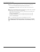
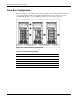
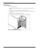
NOTE: When connecting the SATA data cables, be sure to connect them in the following order:
• The connectors on the SATA card from left to right: white, yellow, green, blue.
• The connectors on the SATA backplane from top to bottom: white, yellow, green; blue on the
bottom right corner.
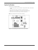
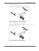
NOTE: There are two SATA LED cables which are tied together using a cable tie. When connecting the
SATA LED cables, be sure to connect them in the following way:
• The two cables should connect to the J14 (hard drive activity indictor) and J15 (hard drive status
indicator) connectors on the SATA card.
• The cable with one end to the J14 connector on the SATA card should connect to the J505
connector on the SATA backplane.
• The cable with one end to the J15 connector on the SATA card should connect to the J507
connector on the SATA backplane.
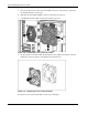
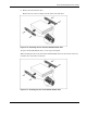
NOTE: You can upgrade by purchasing an HP 6-Port SATA RAID Controller option kit.
When installing the 6-Port SATA RAID Controller, plug the I2C cable into the 3-pin connector labeled
J516 on the SATA backplane. Insert the cable by aligning pin 1 on the cable with pin 1 of connector
J516. For detailed information on how to install the card, refer to the 6-Port SATA RAID controller User
Guide.