
ProLiant ML110 Generation 2 Server Maintenance and Service Guide
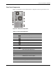


Connectors, Switches, and LEDs
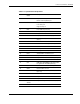
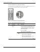
Table 4-3: System Board Components continued
Item Component
Code
Component
26 IDE1 IDE connector
27 SW1 System configuration switch (dip switch)
28 U46 Intel 82801FR I/O controller hub 6 R
(ICH6R) chipset (south bridge)
29 JP1 PCI-X bus speed jumper
Jumper setting:
• 1-2 – 133 MHz PCI-X bus (default)
• 2-3 – 100 MHz PCI-X bus
30 BT1 Maxell CR2032 H 3 V internal lithium
system battery
31 U16 Intel
6702 PXH-V (PCI-X hub) chipset
(PCI bridge)
32 U9 Intel E7220 chipset (north bridge)
33 U10 Intel LGA775 processor socket
34 DIMM1 –
DIMM4
DIMM slots (four)
35 PWRCON2 20-pin ATX system board power connector
36 PWRCON1 4-pin ATX processor power connector
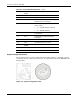
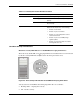
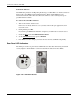
System Configuration Switch
The system board has a system configuration switch (SW1). Figure 4-5 and Table 4-4 show
and describe the use of this switch. In the table, the switch status indicated in bold text is the
default setting.
Figure 4-5: System configuration switch
4-6 HP ProLiant ML110 Generation 2 Server Maintenance and Service Guide