
ProLiant ML110 Generation 2 Server Maintenance and Service Guide

Connectors, Switches, and LEDs
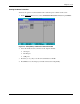
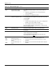
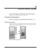
Table 4-1: Front Panel Components
Item Icon Component
1 IDE CD-ROM drive
2 IDE CD-ROM drive mechanical eject hole
3
IDE CD-ROM drive eject button
4 IDE CD-ROM drive activity LED indicator
(amber)
5 Full-height common bays
6
Power/system health LED indicator
(bicolor: green/amber)
7
Power button
• Powers up the server.
• Places the server in standby mode.
• Powers down the server.
8
Hard drive activity LED indicator (amber)
For IDE, SCSI, and non-hot-plug SATA drives
only.
A hot-plug SATA drive installed in the server
has its own set of LED indicators located on
its carrier. For more information, refer to the
“Hard Drive Activity LED Indicators” section in
this chapter.
9
Front USB 2.0 ports (two)
10 HDD cage
The server supports both non-hot-plug and
hot-plug HDD cage models.
11 Torx screws for the HDD cage
4-2 HP ProLiant ML110 Generation 2 Server Maintenance and Service Guide