
ProLiant DL760 Generation 2 Server Maintenance and Service Guide

I/O Module Removal and Replacement Procedures
I/O Expansion Boards
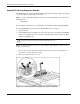
Locating the I/O Expansion Slots
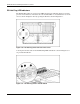
The I/O expansion slots are located in the I/O module and are accessed by opening the I/O lid
as described in “I/O Lid” in Chapter 3. The I/O expansion slots are distributed among one
primary PCI bus and five separate peer PCI-X buses.
WARNING: To reduce the risk of personal injury from hot surfaces, allow the internal
system components to cool before touching them.
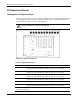
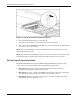
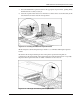
Figure 6-5: Top view of I/O slots
Table 6-1: I/O Expansion Slots
Slot Description
Slots 1 and 2 Bus 19—supports PCI-X expansion boards at 100 MHz and 66 MHz or PCI
expansion boards at 66 MHz and 33 MHz; it is keyed for 3.3 V signaling.
Slots 3 and 4 Bus 15—supports PCI-X expansion boards at 100 MHz and 66 MHz or PCI
expansion boards at 66 MHz and 33 MHz; it is keyed for 3.3 V signaling.
Slots 5 and 6 Bus 11—supports PCI-X expansion boards at 100 MHz and 66 MHz or PCI
expansion boards at 66 MHz and 33 MHz; it is keyed for 3.3 V signaling.
Slots 7 and 8 Bus 7—supports PCI-X expansion boards at 100 MHz and 66 MHz or PCI
expansion boards at 66 MHz and 33 MHz; it is keyed for 3.3 V signaling.
Slot 9 Bus 0—supports PCI expansion boards at 33 MHz; it is keyed for 5 V signaling.
Slots 10 and 11 Bus 3—supports PCI-X expansion boards at 100 MHz and 66 MHz or PCI
expansion boards at 66 MHz and 33 MHz; it is keyed for 3.3 V signaling.
Note: The operating system detects PCI devices in the following slot order:
9-10-11-7-8-5-6-3-4-1-2.
6-6 HP ProLiant DL760 Generation 2 Server Maintenance and Service Guide