
ProLiant DL760 Generation 2 Server Maintenance and Service Guide
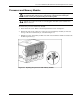
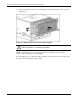

Processor and Memory Module Removal and Replacement Procedures
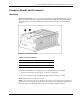
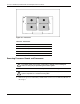
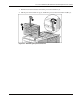
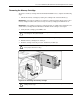
8. Open the processor release lever (1) and remove the processor (2).
NOTE: The processor locking lever now swings from 15 to 135 degrees. Previous generations of
processor sockets required lever movement of only 0 to 90 degrees.
Figure 5-10: Removing the processor
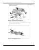
Reverse steps 1through 8 to install a processor and the processor board.
CAUTION: Fully open the processor locking lever before installing a processor. Open
the processor locking lever completely (until it stops) and ensure the alignment pins are in
place. Though the processor may appear to be seated properly when the lever is partially
open and the processor is placed in the socket, the lever must be fully opened to 150 degrees
for the processor to be inserted properly in the socket. If the processor is improperly seated,
damage can occur to the processor and/or system board.
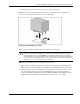
NOTE: Processor board 2 need not be installed for the server to run.
9. Turn on the server. If the system does not power up, verify that the System Interconnect
LED indicators are normal. Refer to “System Interconnect LED Indicators” in Chapter 8.
10. Verify that the processor was installed correctly. Check the processor frequency, cache
size, and socket location by reviewing the POST messages on the system console or
processor information listed under the System Information Menu of the IMD. For more
information, refer to the HP ProLiant DL760 Generation 2 Server User Guide.
HP ProLiant DL760 Generation 2 Server Maintenance and Service Guide 5-9