
ProLiant DL760 Generation 2 Server Maintenance and Service Guide
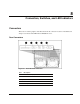

Connectors, Switches, and LED Indicators
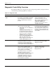
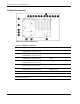
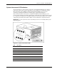
I/O Board Components
Figure 8-2: I/O board components
Table 8-1: I/O Board Components
Item Description Item Description
1, 2 Bus 19 (slots 1 and 2)
64-bit/100-MHz/3-V PCI-X Hot Plug
14 Hot-plug Fan 1 assembly connector
3, 4 Bus 15 (slots 3 and 4)
64-bit/100-MHz/3-V PCI-X Hot Plug
15 Boot block
5, 6 Bus 11 (slots 5 and 6)
64-bit/100-MHz/3-V PCI-X Hot Plug
16 I/O board configuration switches
(SW1)
7, 8 Bus 7 (slots 7 and 8)
64-bit/100-MHz/3-V PCI-X Hot Plug
17 Hot-plug Fan 2 assembly connector
9 Bus 0 (slot 9)
64-bit/100-MHz/3-V PCI Hot Plug
18 NVRAM battery
10, 11 Bus 3 (slots 10 and 11)
64-bit/100-MHz/3-V PCI-X Hot Plug
19 Remote Insight Lights-Out Edition II
cable connector
12 PCI Hot Plug board cable connector 20 Integrated Smart Array 5i controller
13 Non-Maskable Interrupt (NMI) switch 21 Array Enabler board connectors
NOTE: The operating system detects PCI devices in the following slot order:
9-10-11-7-8-5-6-3-4-1-2.
8-2 HP ProLiant DL760 Generation 2 Server Maintenance and Service Guide