
ProLiant DL740 Server Maintenance and Service Guide


Table Of Contents
- HP ProLiant DL740 Server Maintenance and Service Guide
- Notice
- Contents
- About This Guide
- Chapter 1: Illustrated Parts Catalog
- Chapter 2: Service Preparation
- Chapter 3: Chassis Components Removal and Replacement Procedures
- Chapter 4: Host Module Removal and Replacement Procedures
- Chapter 5: Power and Media Module Removal and Replacement Procedures
- Chapter 6: Diagnostic Tools
- Chapter 7: Connectors, Switches, and LED Indicators
- Connectors
- System Board
- Switches
- LED Indicators
- System Power LED Switch
- Unit Identification LED Switches (Front and Rear)
- System Interconnect LED Indicators
- System Attention LED Indicators
- System Activity LED Indicators
- Hot-Plug SCSI Hard Drive LED Indicators
- Power Supply LED Indicators
- Hot-Plug Fan LED Indicators
- PCI Hot Plug LED Indicators
- Memory Cartridge LED Indicators
- DIMM Status LED Indicators
- Chapter 8: Physical, Operating, and Performance Specifications
- Index
Connectors, Switches, and LED Indicators
System Board
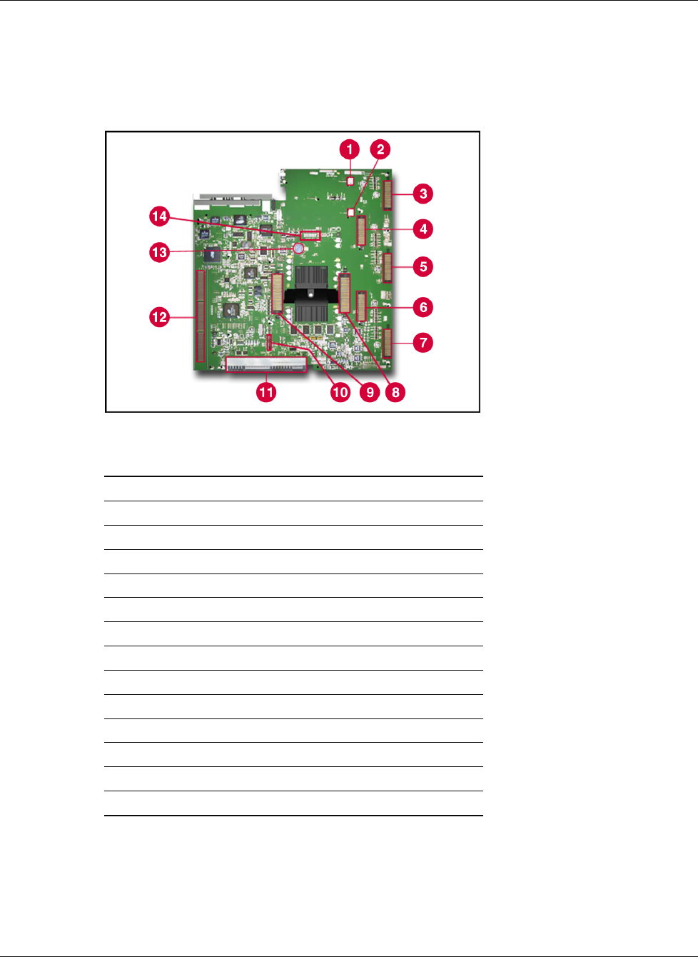
The system board is located in the bottom of the host module. Refer to Figure 7-2 to identify
components on the system board.
Figure 7-2: System board components
Item Description
1 Fan 2 connector
2 Fan 1 connector
3 Memory cartridge 1 connector
4 Memory cartridge 2 connector
5 Memory cartridge 3 connector
6 Memory cartridge 4 connector
7 Memory cartridge 5 connector
8 Processor board 2 connector
9 Processor board 1 connector
10 Remote Insight board connector
11 System/midplane board connector
12 I/O board connector
13 System battery
14 iLO diagnostic LEDs
HP ProLiant DL740 Server Maintenance and Service Guide 7-3
HP CONFIDENTIAL Codename: Jethro Part Number: 270853-004 Last Saved On: 2/10/04 3:53 PM