
ProLiant DL740 Server Maintenance and Service Guide


Table Of Contents
- HP ProLiant DL740 Server Maintenance and Service Guide
- Notice
- Contents
- About This Guide
- Chapter 1: Illustrated Parts Catalog
- Chapter 2: Service Preparation
- Chapter 3: Chassis Components Removal and Replacement Procedures
- Chapter 4: Host Module Removal and Replacement Procedures
- Chapter 5: Power and Media Module Removal and Replacement Procedures
- Chapter 6: Diagnostic Tools
- Chapter 7: Connectors, Switches, and LED Indicators
- Connectors
- System Board
- Switches
- LED Indicators
- System Power LED Switch
- Unit Identification LED Switches (Front and Rear)
- System Interconnect LED Indicators
- System Attention LED Indicators
- System Activity LED Indicators
- Hot-Plug SCSI Hard Drive LED Indicators
- Power Supply LED Indicators
- Hot-Plug Fan LED Indicators
- PCI Hot Plug LED Indicators
- Memory Cartridge LED Indicators
- DIMM Status LED Indicators
- Chapter 8: Physical, Operating, and Performance Specifications
- Index
7
Connectors, Switches, and LED Indicators
Connectors
This section contains graphics and tables that show the connector locations on the
HP ProLiant DL740 server.
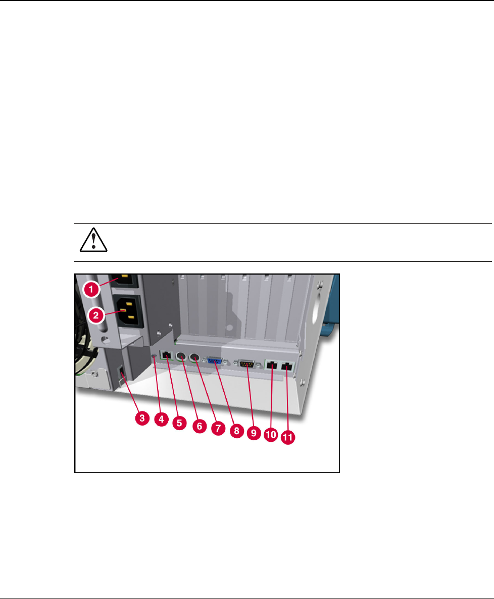
Rear Panel Connectors
Connect any peripheral devices to the connectors located on the rear of the server. Figure 7-1
identifies the peripheral connectors on the back of the server.
WARNING: To reduce the risk of electrical shock or fire, do not plug
telecommunications/telephone connectors into the NIC connectors.
Figure 7-1: Rear panel connectors
HP ProLiant DL740 Server Maintenance and Service Guide 7-1
HP CONFIDENTIAL Codename: Jethro Part Number: 270853-004 Last Saved On: 2/10/04 3:53 PM