
ProLiant DL740 Server Maintenance and Service Guide


Table Of Contents
- HP ProLiant DL740 Server Maintenance and Service Guide
- Notice
- Contents
- About This Guide
- Chapter 1: Illustrated Parts Catalog
- Chapter 2: Service Preparation
- Chapter 3: Chassis Components Removal and Replacement Procedures
- Chapter 4: Host Module Removal and Replacement Procedures
- Chapter 5: Power and Media Module Removal and Replacement Procedures
- Chapter 6: Diagnostic Tools
- Chapter 7: Connectors, Switches, and LED Indicators
- Connectors
- System Board
- Switches
- LED Indicators
- System Power LED Switch
- Unit Identification LED Switches (Front and Rear)
- System Interconnect LED Indicators
- System Attention LED Indicators
- System Activity LED Indicators
- Hot-Plug SCSI Hard Drive LED Indicators
- Power Supply LED Indicators
- Hot-Plug Fan LED Indicators
- PCI Hot Plug LED Indicators
- Memory Cartridge LED Indicators
- DIMM Status LED Indicators
- Chapter 8: Physical, Operating, and Performance Specifications
- Index
Power and Media Module Removal and Replacement Procedures
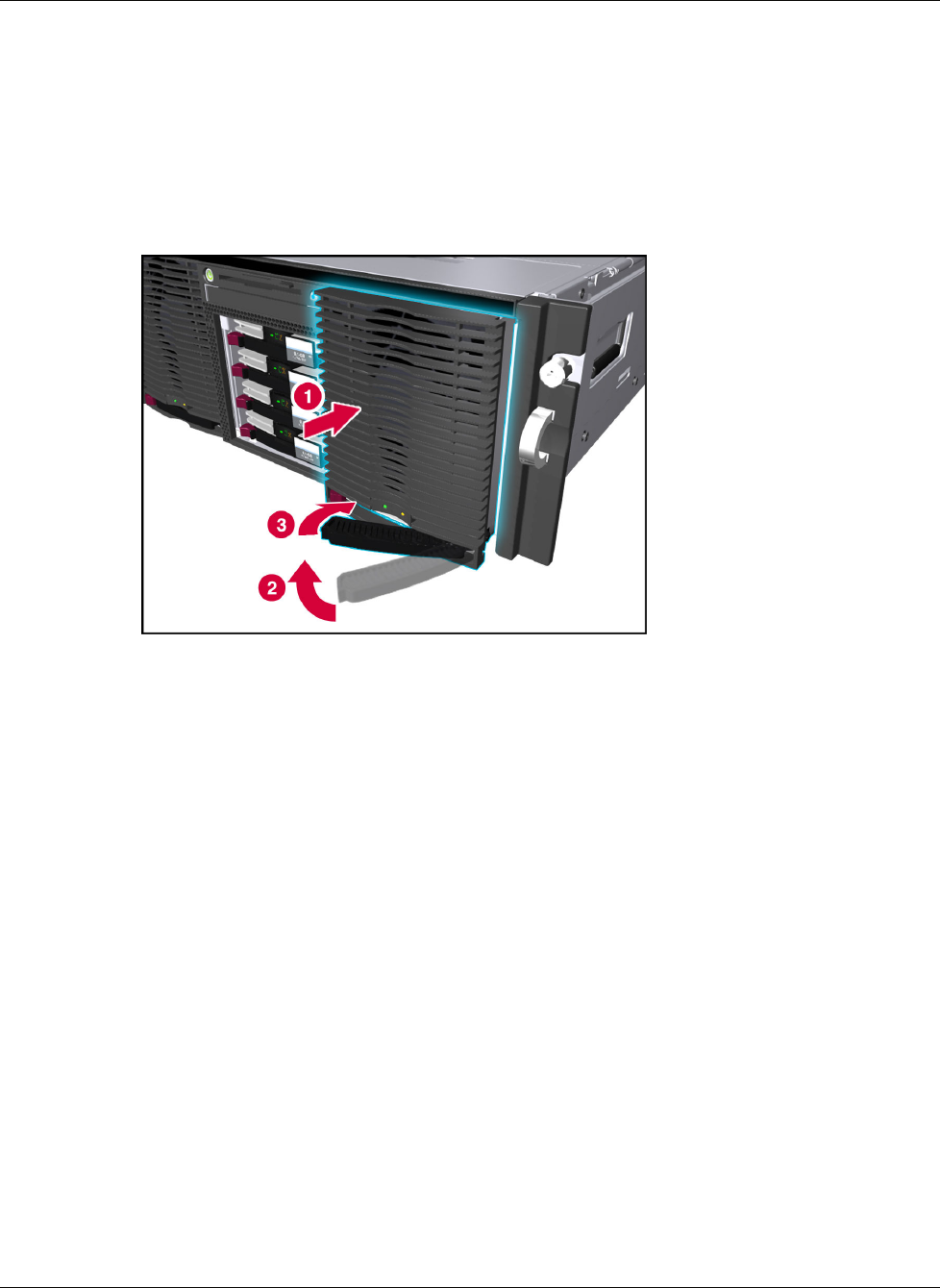
4. Slide the hot-plug power supply into the power supply cage until the supply is seated
securely (1), as shown in Figure 5-4. This action automatically pushes the spring-loaded
trap door open.
5. Rotate the handle inward to lock the power supply into place (2, 3). The power supply fan
starts immediately if the system is running.
IMPORTANT: The power supply fan will start and run at low speed if the system is in Standby mode.
Figure 5-4: Securing the hot-plug power supply
6. Be sure that the AC status LED is green.
If the installation is performed with the system power on, the AC power LED will illuminate
solid. If the installation is performed with the system power off, the AC power LED will
blink to indicate that the power supply is in Standby mode.
5-6 HP ProLiant DL740 Server Maintenance and Service Guide
HP CONFIDENTIAL Codename: Jethro Part Number: 270853-004 Last Saved On: 2/10/04 3:51 PM