
ProLiant DL740 Server Maintenance and Service Guide


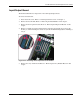

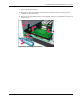


Table Of Contents
- HP ProLiant DL740 Server Maintenance and Service Guide
- Notice
- Contents
- About This Guide
- Chapter 1: Illustrated Parts Catalog
- Chapter 2: Service Preparation
- Chapter 3: Chassis Components Removal and Replacement Procedures
- Chapter 4: Host Module Removal and Replacement Procedures
- Chapter 5: Power and Media Module Removal and Replacement Procedures
- Chapter 6: Diagnostic Tools
- Chapter 7: Connectors, Switches, and LED Indicators
- Connectors
- System Board
- Switches
- LED Indicators
- System Power LED Switch
- Unit Identification LED Switches (Front and Rear)
- System Interconnect LED Indicators
- System Attention LED Indicators
- System Activity LED Indicators
- Hot-Plug SCSI Hard Drive LED Indicators
- Power Supply LED Indicators
- Hot-Plug Fan LED Indicators
- PCI Hot Plug LED Indicators
- Memory Cartridge LED Indicators
- DIMM Status LED Indicators
- Chapter 8: Physical, Operating, and Performance Specifications
- Index

5
Power and Media Module Removal and Replacement
Procedures
The power supplies and mass storage in the HP ProLiant DL740 server are located in the
power and media module. The power and media module can configure a maximum of four
1-inch hot-plug U320 Universal SCSI hard drives or Wide Ultra3 SCSI hard drives.
The power and media module supports two non-hot-plug media drive bays:
• One drive bay occupied by a 1.44-MB diskette drive
• One drive bay occupied by a DVD/CD-ROM drive
CAUTION: Removable media blank bezels and hot-plug drive cage blanking panels must be
installed over unused mass storage and removable media device bays to maintain proper
airflow.
This chapter explains the removal and replacement procedures for the power and media
module and its components and provides cabling guidelines.
HP ProLiant DL740 Server Maintenance and Service Guide 5-1
HP CONFIDENTIAL Codename: Jethro Part Number: 270853-004 Last Saved On: 2/10/04 3:51 PM