
ProLiant DL740 Server Maintenance and Service Guide


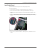

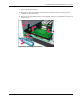


Table Of Contents
- HP ProLiant DL740 Server Maintenance and Service Guide
- Notice
- Contents
- About This Guide
- Chapter 1: Illustrated Parts Catalog
- Chapter 2: Service Preparation
- Chapter 3: Chassis Components Removal and Replacement Procedures
- Chapter 4: Host Module Removal and Replacement Procedures
- Chapter 5: Power and Media Module Removal and Replacement Procedures
- Chapter 6: Diagnostic Tools
- Chapter 7: Connectors, Switches, and LED Indicators
- Connectors
- System Board
- Switches
- LED Indicators
- System Power LED Switch
- Unit Identification LED Switches (Front and Rear)
- System Interconnect LED Indicators
- System Attention LED Indicators
- System Activity LED Indicators
- Hot-Plug SCSI Hard Drive LED Indicators
- Power Supply LED Indicators
- Hot-Plug Fan LED Indicators
- PCI Hot Plug LED Indicators
- Memory Cartridge LED Indicators
- DIMM Status LED Indicators
- Chapter 8: Physical, Operating, and Performance Specifications
- Index
Host Module Removal and Replacement Procedures
4-32 HP ProLiant DL740 Server Maintenance and Service Guide
HP CONFIDENTIAL Codename: Jethro Part Number: 270853-004 Last Saved On: 2/13/04 10:40 AM
6. Locate and remove the Torx tool.
NOTE: If you have installed the integrated array bypass assembly, see “Removing the Integrated Array
Bypass Assembly” in this chapter.
Figure 4-28: Removing the Torx tool
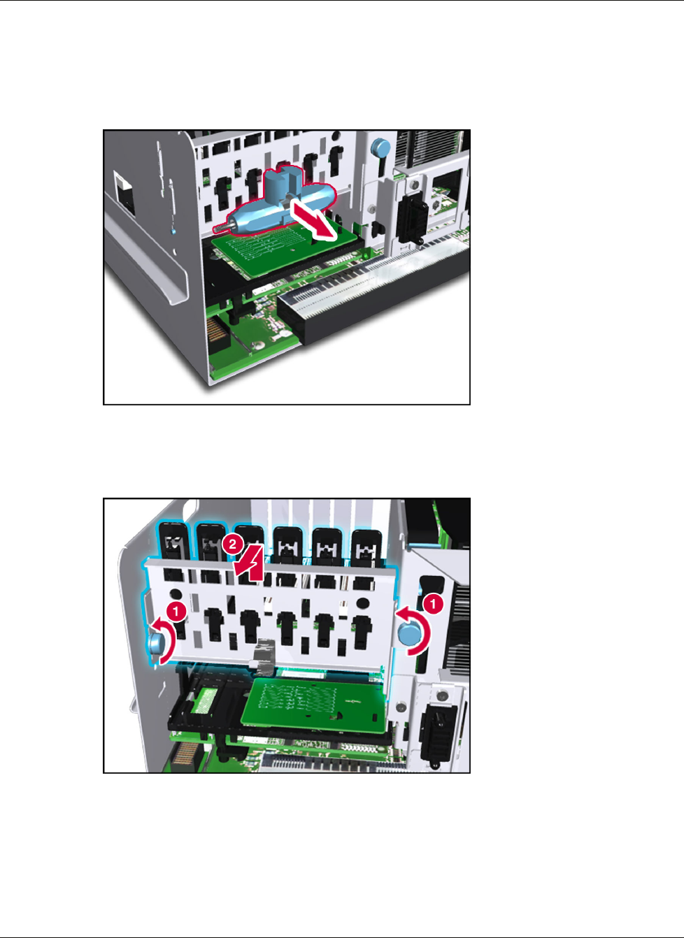
7. Disconnect the I/O expansion board bracket by releasing the thumbscrews (1), and then
lifting the bracket and sliding it towards you (2).
Figure 4-29: Disconnecting the I/O expansion board bracket
8. Disconnect the PCI-X Hot Plug switchboard cable from the PCI-X Hot Plug switchboard.