
ProLiant DL740 Server Maintenance and Service Guide


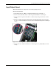

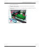


Table Of Contents
- HP ProLiant DL740 Server Maintenance and Service Guide
- Notice
- Contents
- About This Guide
- Chapter 1: Illustrated Parts Catalog
- Chapter 2: Service Preparation
- Chapter 3: Chassis Components Removal and Replacement Procedures
- Chapter 4: Host Module Removal and Replacement Procedures
- Chapter 5: Power and Media Module Removal and Replacement Procedures
- Chapter 6: Diagnostic Tools
- Chapter 7: Connectors, Switches, and LED Indicators
- Connectors
- System Board
- Switches
- LED Indicators
- System Power LED Switch
- Unit Identification LED Switches (Front and Rear)
- System Interconnect LED Indicators
- System Attention LED Indicators
- System Activity LED Indicators
- Hot-Plug SCSI Hard Drive LED Indicators
- Power Supply LED Indicators
- Hot-Plug Fan LED Indicators
- PCI Hot Plug LED Indicators
- Memory Cartridge LED Indicators
- DIMM Status LED Indicators
- Chapter 8: Physical, Operating, and Performance Specifications
- Index

Host Module Removal and Replacement Procedures
HP ProLiant DL740 Server Maintenance and Service Guide 4-31
HP CONFIDENTIAL Codename: Jethro Part Number: 270853-004 Last Saved On: 2/13/04 10:40 AM
Input/Output Board
The ProLiant DL740 server ships with a removable input/output board.
To remove the I/O board:
1. Power down the server. Refer to “Powering Down the Server” in Chapter 2.
2. Remove the host module. Refer to “Removing the Host Module” in this chapter.
3. Remove the I/O expansion boards. Refer to “Removing I/O Expansion Boards” in this
chapter.
4. Remove each I/O expansion board divider by depressing the divider clip to release the
divider (1), and then sliding the divider away from the PCI Hot Plug buttons and lifting it
out (2).
Figure 4-27: Removing the I/O expansion board dividers
5. Remove the array enabler board. Refer to “Removing the Array Enabler Board” in this
chapter.