
ProLiant DL740 Server Maintenance and Service Guide

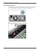


Table Of Contents
- HP ProLiant DL740 Server Maintenance and Service Guide
- Notice
- Contents
- About This Guide
- Chapter 1: Illustrated Parts Catalog
- Chapter 2: Service Preparation
- Chapter 3: Chassis Components Removal and Replacement Procedures
- Chapter 4: Host Module Removal and Replacement Procedures
- Chapter 5: Power and Media Module Removal and Replacement Procedures
- Chapter 6: Diagnostic Tools
- Chapter 7: Connectors, Switches, and LED Indicators
- Connectors
- System Board
- Switches
- LED Indicators
- System Power LED Switch
- Unit Identification LED Switches (Front and Rear)
- System Interconnect LED Indicators
- System Attention LED Indicators
- System Activity LED Indicators
- Hot-Plug SCSI Hard Drive LED Indicators
- Power Supply LED Indicators
- Hot-Plug Fan LED Indicators
- PCI Hot Plug LED Indicators
- Memory Cartridge LED Indicators
- DIMM Status LED Indicators
- Chapter 8: Physical, Operating, and Performance Specifications
- Index
Host Module Removal and Replacement Procedures
HP ProLiant DL740 Server Maintenance and Service Guide 4-25
HP CONFIDENTIAL Codename: Jethro Part Number: 270853-004 Last Saved On: 2/13/04 10:40 AM
Array Enabler Board/Integrated Array Bypass Kit
The SmartArray 5i Controller is routed to the internal drives through the Array Enabler Board
in the host module. The Integrated Array Bypass kit allows you to replace the Array Enabler
board with a connector and cable that you can connect to an optional controller board. For
information on the Integrated Array Bypass kit, refer to the installation instruction included
with the kit.
WARNING: To reduce the risk of personal injury from hot surfaces, allow the internal
system components to cool before touching them.
CAUTION: Back up the data each time you move drive arrays or change the configuration.
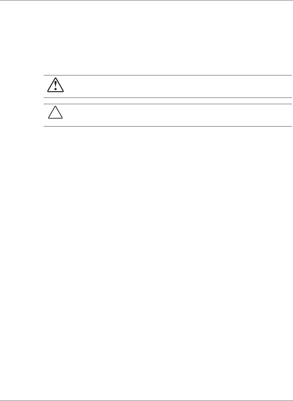
Removing the Array Enabler Board
To remove the Array Enabler board from the host module:
1. Shut down the operating system in an orderly manner as directed in the operating system
instructions.
2. Power down the server. Refer to “Powering Down the Server” in Chapter 2.
3. Disconnect the cables.
4. Slide the server out of the rack.
5. Slide the host module out of the chassis approximately 8 cm (3 in). Refer to “Removing
the Host Module” in this chapter.
6. Open the top access panels. Refer to “Top Access Panels” in Chapter 3.