
ProLiant DL740 Server Maintenance and Service Guide

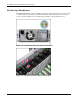


Table Of Contents
- HP ProLiant DL740 Server Maintenance and Service Guide
- Notice
- Contents
- About This Guide
- Chapter 1: Illustrated Parts Catalog
- Chapter 2: Service Preparation
- Chapter 3: Chassis Components Removal and Replacement Procedures
- Chapter 4: Host Module Removal and Replacement Procedures
- Chapter 5: Power and Media Module Removal and Replacement Procedures
- Chapter 6: Diagnostic Tools
- Chapter 7: Connectors, Switches, and LED Indicators
- Connectors
- System Board
- Switches
- LED Indicators
- System Power LED Switch
- Unit Identification LED Switches (Front and Rear)
- System Interconnect LED Indicators
- System Attention LED Indicators
- System Activity LED Indicators
- Hot-Plug SCSI Hard Drive LED Indicators
- Power Supply LED Indicators
- Hot-Plug Fan LED Indicators
- PCI Hot Plug LED Indicators
- Memory Cartridge LED Indicators
- DIMM Status LED Indicators
- Chapter 8: Physical, Operating, and Performance Specifications
- Index

Host Module Removal and Replacement Procedures
4-24 HP ProLiant DL740 Server Maintenance and Service Guide
HP CONFIDENTIAL Codename: Jethro Part Number: 270853-004 Last Saved On: 2/13/04 10:40 AM
7. If you are replacing the board, install the new I/O expansion board.
a. Close the slot release lever.
b. Be sure that the lever latches into the closed position.
c. Reconnect any I/O cables to the new board.
d. Return power to the slot through the PCI Hot Plug button or software application.
The green LED will flash during the power-up transition and will turn on when the
power-up is complete. For more information about PCI Hot Plug LEDs, refer to
“PCI Hot Plug LED Indicators” earlier in this chapter.
8. Close the top access panels.