
ProLiant DL740 Server Maintenance and Service Guide


Table Of Contents
- HP ProLiant DL740 Server Maintenance and Service Guide
- Notice
- Contents
- About This Guide
- Chapter 1: Illustrated Parts Catalog
- Chapter 2: Service Preparation
- Chapter 3: Chassis Components Removal and Replacement Procedures
- Chapter 4: Host Module Removal and Replacement Procedures
- Chapter 5: Power and Media Module Removal and Replacement Procedures
- Chapter 6: Diagnostic Tools
- Chapter 7: Connectors, Switches, and LED Indicators
- Connectors
- System Board
- Switches
- LED Indicators
- System Power LED Switch
- Unit Identification LED Switches (Front and Rear)
- System Interconnect LED Indicators
- System Attention LED Indicators
- System Activity LED Indicators
- Hot-Plug SCSI Hard Drive LED Indicators
- Power Supply LED Indicators
- Hot-Plug Fan LED Indicators
- PCI Hot Plug LED Indicators
- Memory Cartridge LED Indicators
- DIMM Status LED Indicators
- Chapter 8: Physical, Operating, and Performance Specifications
- Index
Host Module Removal and Replacement Procedures
HP ProLiant DL740 Server Maintenance and Service Guide 4-23
HP CONFIDENTIAL Codename: Jethro Part Number: 270853-004 Last Saved On: 2/13/04 10:40 AM
Removing or Replacing a PCI Hot Plug Expansion Board
To remove or replace a PCI Hot Plug expansion board:
1. Open the top access door of the server.
2. Use the PCI Hot Plug button or software application to notify the system to turn off
power to the slot. Pushing the PCI Hot Plug button notifies the system to shut down
operation of the expansion board; lifting the lever actually powers down the expansion
slot. The green LED flashes during the power-down transition and turns off when the
power-down process is complete. For more information about PCI Hot Plug LEDs, see
“PCI Hot Plug LED Indicators” earlier in this chapter.
CAUTION: To avoid system power-down and subsequent data loss, do not open the slot
release lever unless the green PCI Hot Plug LED of the slot is off.
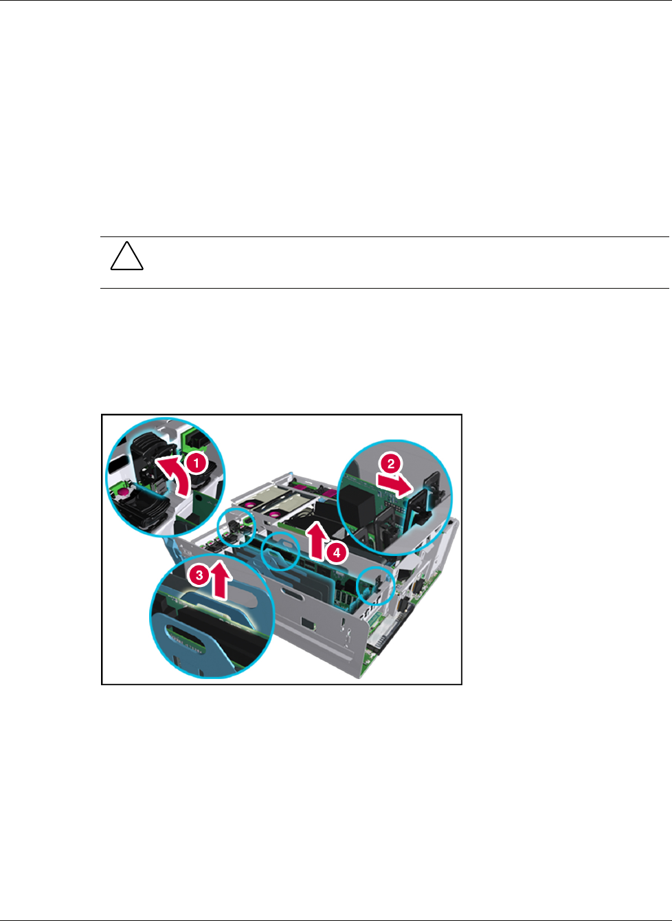
3. Disconnect the cables to the PCI/PCI-X board when the green LED of the slot is off.
4. Press on the top of the appropriate expansion slot release lever (1) and open the lever
toward the rear of the expansion slot (2).
5. Unseat the expansion board by pulling up on the plastic tab (3), and then lift the board out
of the server (4).
Figure 4-21: Removing an I/O expansion board
6. If you are only removing the board and not replacing it, install an expansion slot cover.
a. Close the slot release lever.
b. Be sure that the lever latches into the closed position.